Page 31
Ignition SystemsJB Manual
(2 1/2”)
(3 1/2”)
7/8”
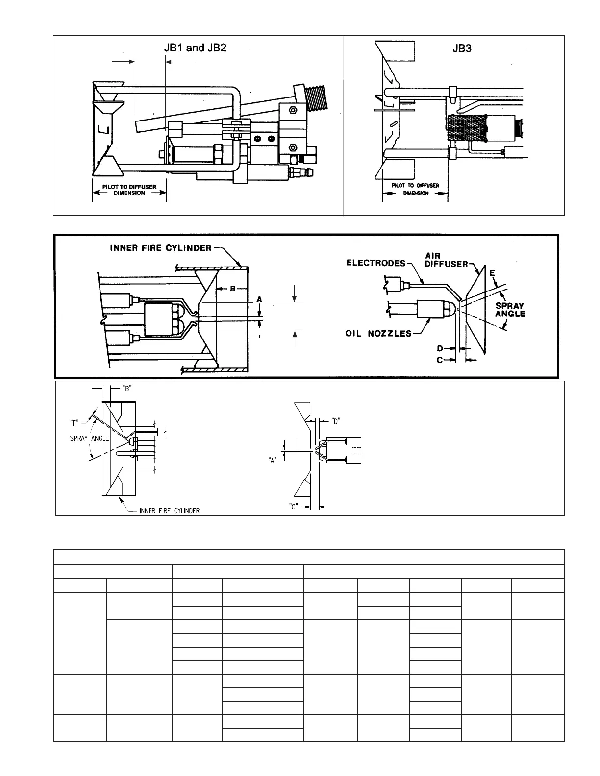
Figure H-3
Figure H-4
FIGURE H-7 DIMENSION TABLE FOR DIRECT SPARK OIL IGNITION (Pressure Atomizing)
BURNER DATA NOZZLE DATA ADJUSTMENT SETTINGS (Inches)
Model Diffuser I.D. Qty. Spray Angle
o
A B C D E
JB1
1
1 30
1/8
1/2 1/2
5/16 1/4
1 45 3/8 3/8
1 1/2”
1 30
1/8 1 1/2
7/8
5/16 1/4
1 45 3/4
2 30 1/4
2 45 1.4
JB2
1 3/4” 2
30
1/8 1 1/2
3/4
5/16 1/4
45 5/8
60 1/2
JB3
2 7/8 3
60
1/8 1 1/2
5/8
3/8 1/8
80 7/16
Diffuser
ID
FIGURE H-6
TRIPLE NOZZLE
FIGURE H-5 DIRECT SPARK PRESSURE ATOMIZING OIL IGNITION (See Table Below)
DIRECT SPARK OIL IGNITION (See Table Below)
Note: These represent initial nozzle settings. The final position will be determined in the start-up process.
 Loading...
