Do you have a question about the Weco 5K3-XP-EU and is the answer not in the manual?
Guidelines for storing battery modules in original packaging.
How temperature impacts chemical reactions and battery capacity.
Relationship between discharge depth and battery cycle life.
Importance of proper charging settings to avoid over/undercharging.
Conditions and limitations for battery warranty coverage.
Details the scope of the manual and target audience.
Information on applying installation guidance for low voltage inverters.
Note regarding product specifications and potential changes.
Guidelines for safe handling, tool usage, and personal protection.
Warning about the module's weight and the need for careful handling.
Hazards associated with Lithium Iron Phosphate battery and safety precautions.
Guidelines for safe storage, transport, and handling of batteries.
Procedures for unpacking and safely handling battery modules.
Overview of wall mounting and stack mounting configurations.
Dimensions of the battery module for wall mounting.
Steps for installing the wall bracket and mounting the battery.
Steps for stacking battery modules horizontally.
Explanation of the purpose and function of each battery terminal.
Steps to verify the battery module before initial operation.
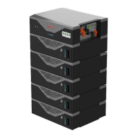
Introduction to the WeCo 5K3-XP-EU as an energy storage system.
Description of the nameplate label and product identification.
List of standard accessories included with the battery module kit.
List of tools required for installation.
Essential personal protective equipment and insulated tools for safe installation.
Instructions for wiring and setting up the low voltage battery module.
Identification of low voltage and high voltage connection terminals.
Pin definition for the CAN communication port on the battery.
Configuration of DIP switches for low voltage operation.
DIP switch settings for parallel configuration in low voltage mode.
Explanation of visual indicators on the battery module.
Procedures for activating and shutting down the battery module.
Overview of setting up multiple modules in parallel for low voltage.
Specific DIP switch settings for parallel low voltage configuration.
Automatic ID assignment and DIP configuration for parallel clusters.
Process for waking up the battery module using the RUN button.
DIP switch settings and data connection for single cluster setup.
Instructions for making parallel power cable connections.
Torque specifications for power cable connections and checking frequency.
Power and data connections for a single stack of up to 15 modules.
Explanation of LED bar indicators for status and errors.
Controls on the front panel for starting and shutting down the battery.
Procedure to start the battery module from the front panel.
Procedure to shut down the battery module from the front panel.
Procedure for force charging a low battery.
Requirements and steps for configuring batteries in parallel.
Steps to activate parallel batteries starting from the master module.
Procedure to shut down parallel batteries.
Connecting batteries in parallel with inverter BMS communication.
How to connect power cables for a single cluster of batteries.
Using the CAN Hub for systems with multiple clusters.
Physical dimensions of the Low Voltage CAN HUB.
Control logic and protection limits for the battery system.
General description of the CAN Hub's system role.
Details on different multi-cluster configuration setups.
Setting up Master IDs and connection diagrams for multi-cluster systems.
Example of power connection for multi-cluster systems.
Conceptual diagram of a cluster setup with multiple batteries.
Conceptual diagram of connections between master modules of multiple clusters.
List of accessories for cluster configuration.
Contents of the single cluster configuration kit.
Description of the multi-cluster hub device.
Pinout details for connecting battery to inverter via CAN.
Instructions to download the WECO BMS PC software from the website.
Steps to select the module setting program in the software.
Connecting the RS232-USB converter to the battery module's operator port.
Selecting the correct COM port in the PC software for communication.
Displayed software page after successful communication establishment.
Selecting the correct number of batteries for cluster configuration in the software.
Modifying the low voltage protocol for communication with different inverters.
Steps for updating the battery module firmware using the PC software.
Limits for charging and discharging current and voltage set by the inverter.
Details of the 10-year performance guarantee and compliance requirements.
Actions to take in case of battery or inverter alarms and warnings.
| Brand | Weco |
|---|---|
| Model | 5K3-XP-EU |
| Category | Battery Pack |
| Language | English |