Do you have a question about the Weco HeSU 5K3-LV HV and is the answer not in the manual?
| Nominal Voltage | 51.2 V |
|---|---|
| Nominal Capacity | 100 Ah |
| Energy | 5.12 kWh |
| Usable Energy | 4.6 kWh |
| Communication | CAN, RS485 |
| Protection Level | IP65 |
| Capacity | 100 Ah |
| Operating Temperature | -20°C to 55°C |
| Communication Interface | CAN, RS485 |
| Battery Type | Lithium Iron Phosphate (LiFePO4) |
| Cycle Life | 6000 cycles |
Procedures for handling and lifting the battery module from its packaging.
Instructions for mounting the battery module on a wall or stacking it.
Defines the function and layout of each terminal on the battery.
Steps to perform a pre-operational check after unboxing the battery.
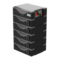
Overview of the WeCo 5K3 LV-HV module for energy storage systems.
Guide to identifying module specifications and characteristics.
Details on the nameplate label and product identification.
List of standard accessories included in the LV kit for a single module.
Lists required tools for installing the battery module.
Specifies essential PPE for safe installation and operation.
Instructions for wiring and setting up the module in low voltage configurations.
Details on making the correct battery connections for low voltage.
Defines the function of each terminal for LV connections.
Configuration of DIP switches for various LV operating modes.
DIP switch settings for a single standalone battery module.
DIP switch settings for a master-slave parallel connection.
DIP switch settings for a 3-module parallel connection.
DIP switch settings for a 4-module parallel connection.
DIP switch settings for a 5-module parallel connection.
Guidelines for wiring multiple batteries in parallel.
Power and data connection example for a 5-module stack.
Procedures for activating and shutting down battery modules.
Explanation of LED indicators on the module for status.
Controls for starting and stopping a standalone battery.
Steps for configuring batteries in a parallel system.
List of compatible inverters and max modules per cluster.
Inverters compatible with direct parallel CAN communication.
LV direct parallel configuration without BMS communication.
General overview of multi-cluster system configurations.
Setup and use of the CAN Hub for multi-cluster systems.
Physical dimensions of the CAN Hub device.
Control logic and current protection limits for clusters.
Description of the CAN Hub's role in system communication.
Usage of special bus bars for parallel battery configurations.
Various configurations for multi-cluster systems using the Hub.
Accessories required for cluster configuration.
Settings for inverters without communication ports.
Overview of the WeCo 5K3 HV module for high voltage energy storage.
Guide to identifying module specifications and characteristics for HV.
Details on the nameplate label and product identification for HV.
List of standard accessories for the HV kit.
Lists required tools for installing the HV battery module.
Specifies essential PPE for safe HV installation.
Instructions for wiring and setting up the module in high voltage.
Details on making the correct battery connections for HV.
Defines the function of each terminal for HV connections.
Possible module configurations and voltage limits for HV Box.
Configuration of DIP switches for HV operation.
Setting up the CAN communication loop for HV serial towers.
Guidelines for wiring batteries in series for HV configuration.
Power connection details for a 12-module HV stack.
Data connection example for a 12-module HV stack.
Power connection steps for HV Box and modules.
Steps to connect a single HV Box to an inverter.
Connecting multiple HV Boxes for BATCH 40 and above.
Setting HV Box addresses for all batches using DIP switches.
Explanation of LED indicators for HV Box status.
Controls for forced charging of standalone HV batteries.
Procedure for low battery force charging in HV configuration.
Compatible inverters and max modules per cluster for HV.
HV Box compatibility with inverters via CAN communication.
HV connection without CAN communication.