`çãéäÉíÉ=háí=mÉíÉêÄáäí=
`çãéäÉíáçå=çÑ=~ëëÉãÄäó=Öêçìéë
908
908
13
13
1390
789
30
3
13
26
13
13
26
13
3
32
33
18
20
27
52
20
2
29
36
55
19
19
2
20
5
18
20
27
52
53
53
29
30
30
36
5
32
33
13
3
13
26
3
13
13
26
109
34
34
41
41
41
41
42
42
4
4
808
41-e.DOC / K-Peter Page 5
V mêÉîáÉï=çÑ=íÜÉ==
ÉäÉÅíêáÅ~ä=ëóëíÉã=áåëí~ää~íáçå=
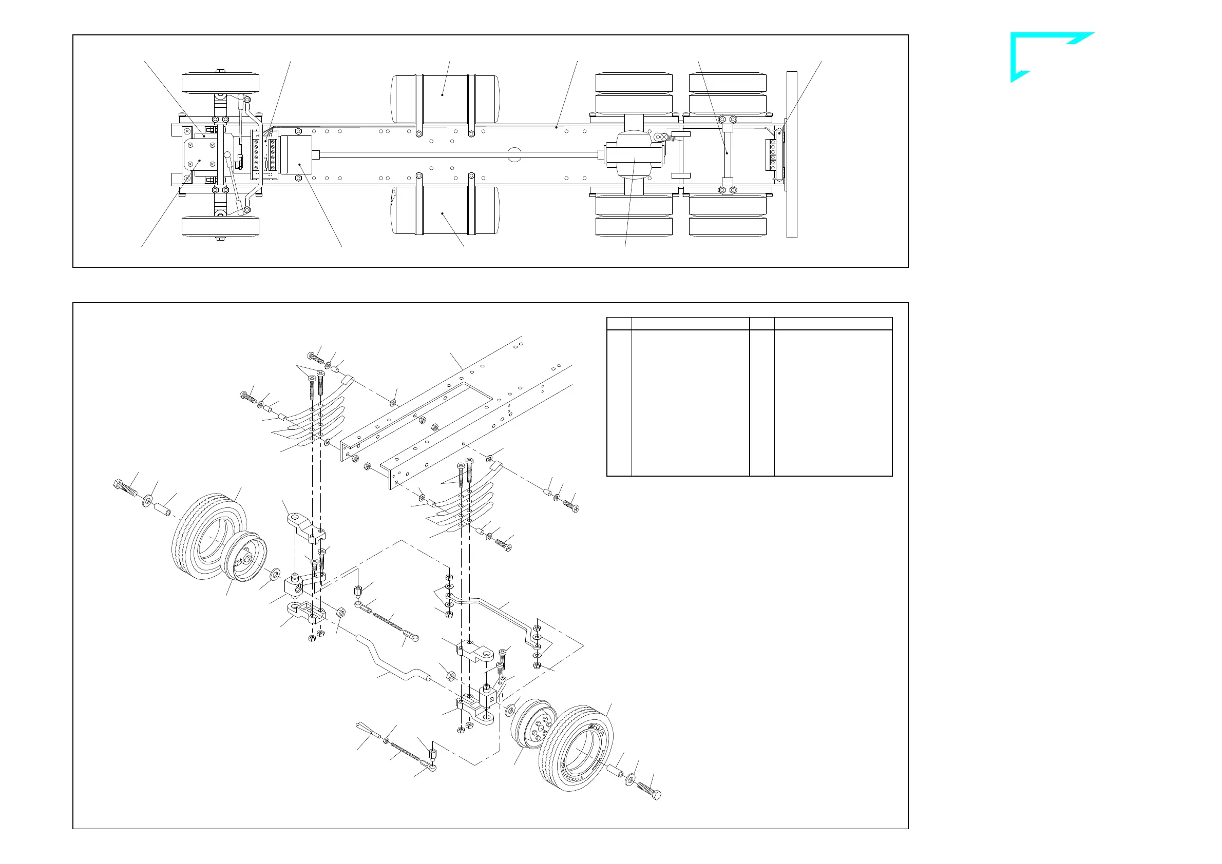
The illustration at the left shows the locations of the PCBs and the
routing of the ribbon cable beneath the frame. The cable will have to
be installed underneath the frame before the electrical devices are
installed in their entirety. The cable should run between the frame
and the axles, the fifth-wheel shaft and the screws used to affix the
tank. If the cable were to be laid later it would be necessary to disas-
semble some components already installed.
The best course of action is to read all the information on the electri-
cal system in Chapter 23 before you begin assembling the compo-
nents on the frame. This will give you an idea of which components
will be connected by cable.
NM cêçåí=~ñäÉ=ëÉÅíáçå=
10.1 Mounting the suspension with front axle
First install the screws 3 together with washers 13, bushings 26, and
M3 nuts at the rearward holes in the frame, provided for attaching the
springs. Then attach the open ends of the two long spring leaves 32
at the bushings and use an identical set of parts to screw the closed
ends to the front of the frame 45. One nut 19 each is pressed into the
hexagonal depressions at the steering lever 42. Use two screws 5
and M3 nuts to attach to the long spring leafs, previously mounted,
two medium spring leaves 33 and a short spring leaf 34 along with
two half-axle guards 41, into which the front axle 55 and steering le-
ver 42 have been inserted.
Before tightening down the screws 5 ensure that the spring sets
are not under tension and can move freely.
10.2 Mounting the wheels and steering linkage
First mount the standard tyres 53 on the rims 52. Then use screws
18 and one washer 20 each in front of and behind the axle tube 27
located in the hub to bolt the wheels to the steering lever, using the
nut already inserted. To the outer holes on the steering levers fix two
screws 4 along with nuts M3. To this unit add now the track rod 1390
using washers 13 and stop nuts 908; do not tighten the stop nuts but
leave the track rod moveable.
With screws 2 fix two ball bolts 29 to the inner holes on the steering
levers for the attachment of the steering rods. To a steering rod 36
add one nut 109, fork head 789 and ball socket 30. The steering rod
has to be bent slightly, depending on the size of the servo unit. After-
wards clip this steering rod for the servo linking to the left-hand ball
bolt. For operation of the blinker switch, add to the right-hand ball
bolt another steering rod 36, equipped with two ball sockets 30. Ad-
just the distance between the ball sockets so that the wheels are in
the straight-ahead position when the lever of the blinker switch is in
its neutral setting.
Front axle section ill. 10
View from below showing the location of components mounted onto the frame ill. 9
Steering servo Front PCB Tank Ribbon cable Rear axle Rear PCB
Blinker switch Gear Speed controller Differential
Qty.
No. Assembly part
4
33
Spring medium, “AF“
2
34
Spring short, “AF“
2
36
Steering rod M2 x 50
4
41
Half-axle guard
2
42
Steering lever
2
52
Rim, chromed
2
53
Standard tyre
“Ecocontrol“
1
55
Front axle
1
109
Nut M2
1
789
Fork head
1
808
Frame “XL“, 590mm
2
908
Stop nut M3
1
1390
Track rod, flat
Qty.
No. Assembly part
10
---
Nut M3
2
2
Screw M3 x 8
4
3
Screw M3 x 12
2
4
Screw M3 x 16
4
5
Screw M3 x 20
12
13
Washer 3.2
2
18
Hex head screw
M4 x 25
2
19
Nut M4
4
20
Washer 4.3
4
26
Bushing 4 x 0.5 x 7
2
27
Axle tube
2
29
Ball bolt M3
3
30
Ball socket
2
32
Spring long, “AF“
B-41-3
B-44-9
peter


 To Next Page
 Loading...