`çãéäÉíÉ=háí=mÉíÉêÄáäí=
`çãéäÉíáçå=çÑ=~ëëÉãÄäó=Öêçìéë
655
713
706
19
15
13
707
26
13
707
26
713
289
706
15
19
1263
4
4
111
111
15
15
15
15
15
15
2
15
15
56
498
840
839
839
838
1
15
15
15
2
355
355
355
835
728
729
730
5
1
730
729
1
728
5
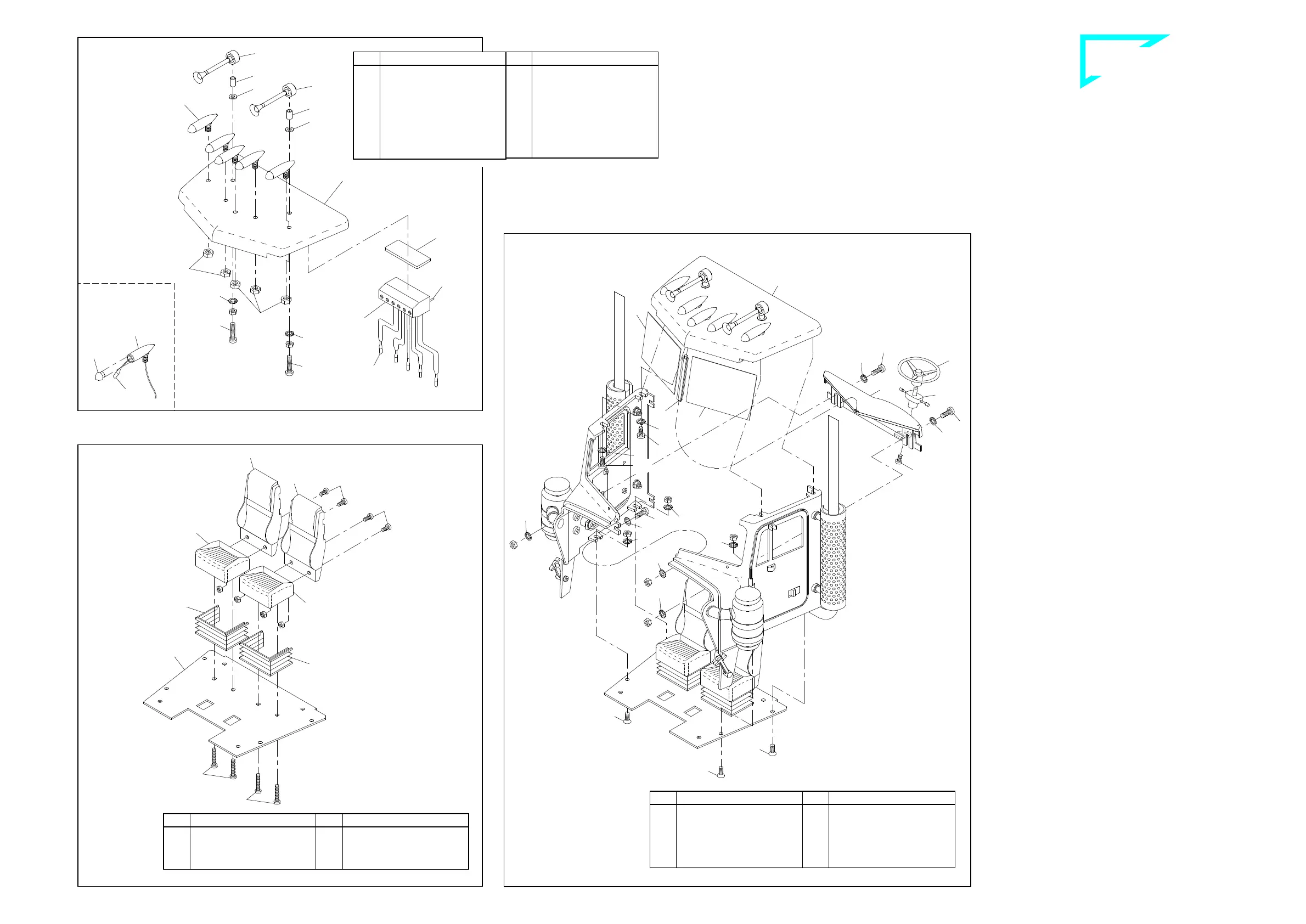
S oççÑ=ëÉÅíáçå=
6.1 Horns
The horns 707 are fitted with bushings 26 and washers 13 and then
affixed, through the holes provided in the roof 1263, using screws 4,
nuts M3 and serrated washers 15.
6.2 Roof lamps
Install a bulb 713 in each of the roof lamps 706, threading the leads
through the lamp housings first. The cables are easier to thread if
you twist the two conductors together and bend the ends slightly.
Pointed tweezers can help in pulling the cable through. Do not pull
the bulbs too far into the lamp housings; the bulbs should protrude by
2 to 3 mm. After the roof lamp lenses 289 have been pressed onto
the lamp housings, the housings are inserted in the holes in the roof
and secured with nuts 19.
The bulb leads and the red/black cable from the switch panel are at-
tached to the terminal strip - see Section 23.3 and ill. 23. Use adhe-
sive pads 655 to affix the terminal strip under the roof so that the
cables are not visible inside the cab.
T ^íí~ÅÜãÉåí=çÑ==
íÜÉ=ëÉ~íë=çåíç=íÜÉ=Ñäççê=éä~íÉ=
Fix the seat backs 728 with screws 1 and nuts M3 onto the seat so-
ckets 729. Then press the swing seats 730 onto the seat sockets
and fix the complete seat units with screws 5 onto the floor plate
835..
U ^ëëÉãÄäó=çÑ=íÜÉ=Å~Ä=
Lay the right and the left front units together and fix them with each
other underneath the windows with screws 2, two serrated washers
15 and nuts M3. Lay then the roof 837 onto both front units and
screw it up with four screws 111 and serrated washers 15. Make su-
re that along the full line the distance between roof and front parts
has to be the same. Afterwards set the floor plate from underneath
onto the front parts and fix it with countersunk screws 355, serrated
washers 15 and nuts M3.
Pin the centre strut 838 from underneath into the recess of the roof
and lay the centre strut with the inclined sides against the front parts.
Lay both front screens 839 into the lateral groove of the centre strut
as well as into the left and the right groove of the roof. Make sure
that the screens catch the projected rest of the front units.
Take now the steering wheel 56 and press it onto the pin of the
switch 498. The proper switch has then to be fixed onto the dashbo-
ard with screw 1. Remove the decals from their sheet 841 and apply
them on the left and right side of the dashboard. Lay then the dash-
board from inside against the front parts and fix it onto the door hin-
ges with screws 2, serrated washers 15 and nuts M3. When correctly
assembled, the fore edge of the dashboard presses the centre strut
and the front screens against the front units.
41-e.DOC / K-Peter Page 4
Assembly of the cab ill. 8
Roof section ill. 6
Attachment of the seats onto the floor plate ill. 7
Roof
Terminal
strip for
roof lamps
For threading the
bulb leads see
proper text
Please
clip off
the sol-
der pins
Qty.
No. Assembly part
1
655
Adhesive pad,
double-sided
5
706
Roof lamp, chromed
2
707
Horn
5
713
Bulb 3V
1
1263
Cab roof, Compl. kit Pe-
terbilt “C“
1
---
Terminal strip for roof
lamps, 6-pole
Qty.
No. Assembly part
2
---
Nut M3
2
4
Screw M3 x 16
2
13
Washer 3.2
2
15
Serrated washer 3.2
5
19
Nut M4
2
26
Bushing 4 x 0.5 x 7
5
289
Lens for roof lamp,
orange
Qty.
No. Assembly part
2
729
Socket, bucket seat
2
730
Foot, bucket seat
1
835
Floor plate, Peterbilt
Qty.
No. Assembly part
4
---
Nut M3
4
1
Screw M3 x 6
4
5
Screw M3 x 20
2
728
Back, bucket seat
Qty.
No. Assembly part
4
355
Counters. screw M3 x 8
1
498
Switch dashboard
1
838
Centre strut, windscreen
2
839
Windscreen (half)
1
840
Dashboard Peterbilt
1
841
Decal sheet, Peterbilt
Qty.
No. Assembly part
7
---
Nut M3
1
1
Screw M3 x 6
3
2
Screw M3 x 8
14
15
Serrated washer 3.2
1
56
Steering wheel
4
111
Self-cutting screw M3 x 8
B-41-1
B-41-2
B-220-5
 Loading...