`çãéäÉíÉ=háí=mÉíÉêÄáäí=
`çãéäÉíáçå=çÑ=~ëëÉãÄäó=Öêçìéë
15
15
10
10
829
830
96
12
16
26
13
93
16
26
13
12
96
95
383
372
383
483
831
26
13
13
833
834
24
3
832
114
472
472
469
470
470
282
21
21
397
397
823
823
824
824
820
821
822
822
825
825
826
826
827
827
828
828
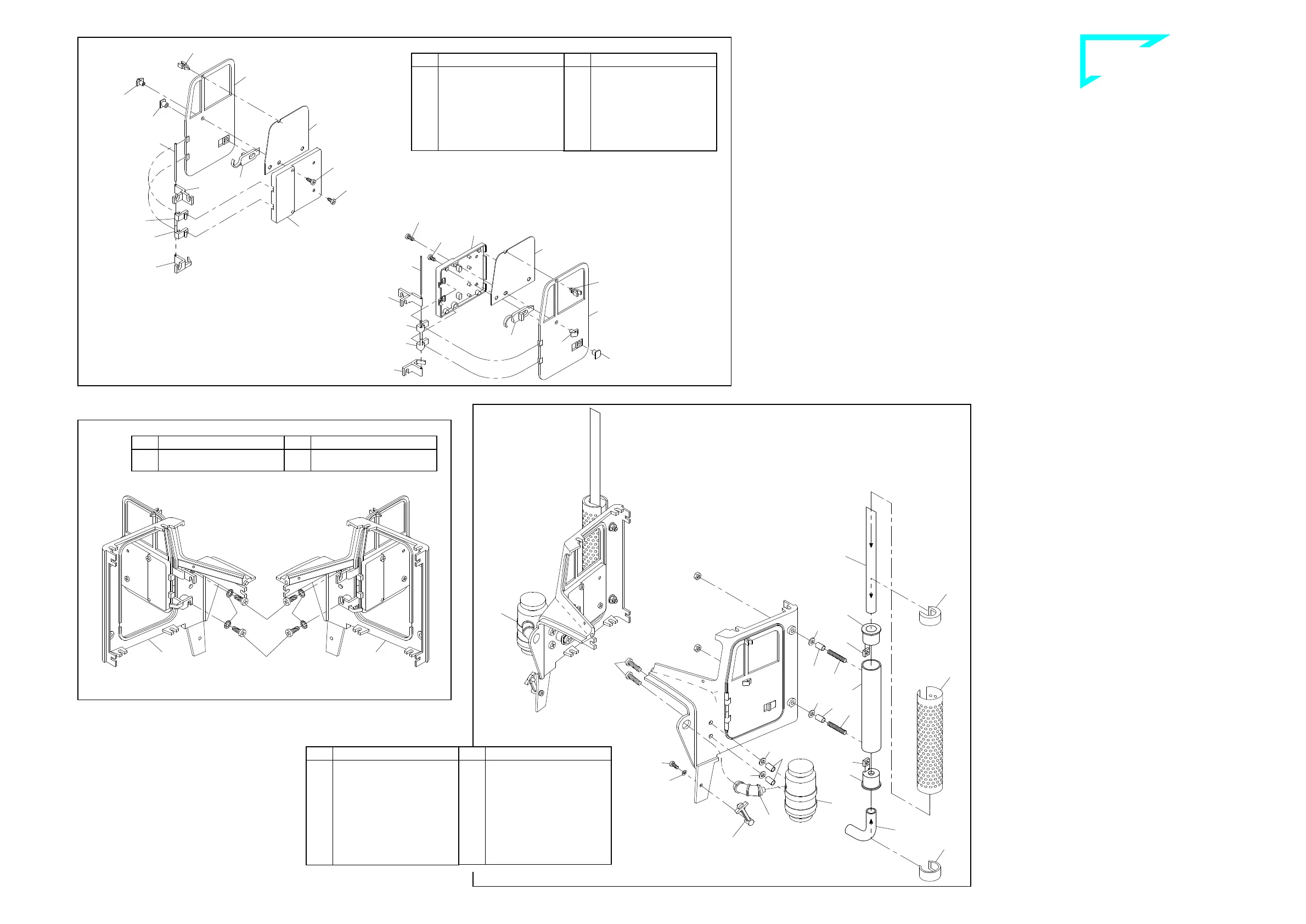
P ^ëëÉãÄäó=çÑ=íÜÉ=Çççêë=
Start assembling the door hinges. For this purpose press the pins
827 into the holes of the door hinges 825, 823, 824 and 826. Please
note the different sequence on the left and the right side. Then lay
the noses of the door hinges 823 and 824 into the clamping device of
the inside door coating 822.
Press both outer holes of the side windows 828 (remove first the foil
on both sides) onto the pins of the inside door coating. Then lay the
door lock 472 into the inside door coating, press the mirror support
470 into the holes of the doors 820 and 821 as well as into the holes
of the side windows and the inside door coating. Tighten the mirror
supports using screws 21. Lay as well the lock guides 469 into the
recessed door holes and the door locks and fix them with screws 21.
Finally press the clips 282 into the upper bores of the doors; the side
windows are thereby additionally fixed.
Q ^íí~ÅÜãÉåí=çÑ=íÜÉ=Çççêë=çåíç==
íÜÉ=Ñêçåí=é~åÉäë=
Prepare both front panels 829 and 830 for the attachment of the
doors. For this purpose cut with one of the self-cutting screws 10
threadings into the bores of the front panels (use some grease or va-
seline). Now lay the prepared doors from outside onto the door fra-
mes of the front panels and fix the door hinges with screws 10 and
serrated washers 15 onto the front panels. It is important to adjust
the doors before you finally tighten them. The additional fixing points
of the upper door hinges serve for mounting the dashboard.
R cáåáëÜáåÖ=çÑ=íÜÉ=Ñêçåí=ìåáíë=
5.1 Air filter
Press both air tubes 833 into the holes of the air filters 831 and 832.
Then add the air filters onto the front units with bushings 26, washers
13 and screws 3. Now press the air tubes into the holes of the front
units.
5.2 Exhaust system
For the attachment of the exhaust system slide each one square nut
12 into the recesses of the exhaust caps 96. Slide then the exhaust
caps that way into the mufflers 93 that the square nuts lay behind the
holes. From top insert the exhaust tail pipes 95 that way that the
point shows frontwards when adding the exhaust system to the front
units. Press the exhaust tail pipes into the exhaust caps until they
catch, then clamp them using studs 16. By the same way add the
exhaust manifolds 483 (the longer side of the manifold has to be fi-
xed inside the exhaust cap 96).
Afterwards slide each one bushing 26 and one washer 13 onto the
studs. With the studs insert the exhaust systems laterally through the
rear holes of the front units; then fix them with nuts M3. Slide the ex-
haust shields 372 over the mufflers 93, insert the fixing caps 383 and
clamp the shields on. One may even increase the wedging effect of
the shields by careful squeezing.
5.3 Locks for the hood
Now use screws 114 and washers 24 to attach both locking devices
834 onto the lower shields of the front units.
41-e.DOC / K-Peter Page 3
Finishing of the front units ill. 5
Attachment of the doors onto the front panels ill. 4
Assembly of the doors ill. 3
Qty.
No. Assembly part
2
822
Inside door coating
2
823
Door hinge 1
2
824
Door hinge 2
2
825
Door hinge, top
2
826
Door hinge, bottom
2
827
Pin for door hinge
∅1 x 36mm
2
828
Side window
Qty.
No. Assembly part
2
21
Tapping screw 2.2 x 4.5
2
282
Fixing clip
2
397
Tapping screw 2.2 x 6.5
2
469
Lock guide, door
2
470
Mirror hinge, bottom
2
472
Door lock
1
820
Door -lh-, Peterbilt
1
821
Door -rh-, Peterbilt
Qty.
No. Assembly part
1
829
Front panel -lh-, Peterb.
1
830
Front panel -rh-, Peterb.
Qty.
No. Assembly part
4
10
Self-cutting screw M3 x 6
4
15
Serrated washer 3.2
Qty.
No. Assembly part
2
114
Screw M2 x 6
2
372
Exhaust shield, chromed
4
383
Fixing cap for exhaust
shield
2
483
Exhaust manifold
1
831
Air filter -lh-, Peterbilt
1
832
Air filter -rh-, Peterbilt
2
833
Air tube
2
834
Locking device for hood
Qty.
No. Assembly part
4
---
Nut M3
4
3
Screw M3 x 12
4
12
Square nut M3
8
13
Washer 3.2
4
16
Stud bolt M3 x 18
2
24
Washer 2.2
8
26
Bushing 4 x 0.5 x 7
2
93
Muffler 80mm
2
95
Exhaust tail pipe
4
96
Exhaust cap
B-220-2
B-220-3
B-220-4
 Loading...