`çãéäÉíÉ=háí=mÉíÉêÄáäí=
`çãéäÉíáçå=çÑ=~ëëÉãÄäó=Öêçìéë
114
114
114
114
843
843
843
846
846
846
846
846
846
846
845
845
844
844
369
369
369
368
368
370
370
370
370
21
21
21
21
742
21
21
843
742
742
720
721
721
722
719
724
564
564
2
58
391
2
60
62
61
63
59
708
64
41-e.DOC / K-Peter Page 7
NP píÉéÄç~êÇ=ëÉÅíáçå=
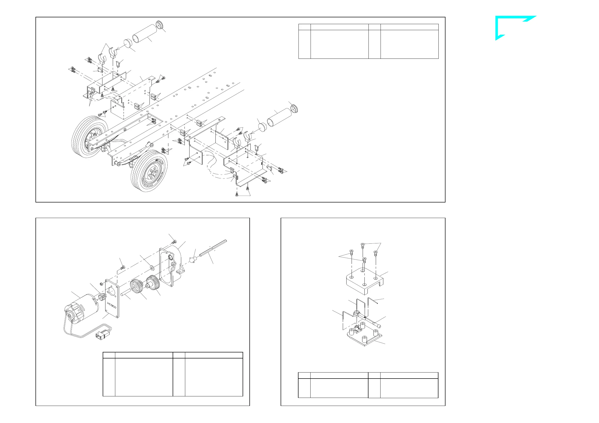
First fix the threaded bushings 843 with screws 742 laterally onto the
sides of the frame and afterwards screw the bridging clamps 369
with screws 21 onto the stepboard plates 845. Into their slots pin the
plate connections 846, lay the plates onto the stepboards 844 and fix
them with screws 21 onto the stepboards. The right and the left step-
board are then secured with screws 114 onto the threaded bushings.
Into the case for air tank 368 press then on both sides each one co-
ver 370 and slide the case into the bridging clamps 369.
NQ jçìåíáåÖ=íÜÉ=ãçíçê=~åÇ=ÖÉ~êÄçñ=
Use screws 2 to bolt the gear cover 59 to the motor 708 (we supply
the white motor pinion 60 (14t.) already mounted to the motor shaft).
Before assembling the gearing lubricate the gears and shafts lightly
with Vaseline. Then clip the joint ball 64 in the gear wheel 62. Lay this
gear wheel, the double pinion 61 with shaft 63 and -not to forget!- the
shim 391 in the gear housing 58 and use screws 2 and M3 nuts to
secure the gear housing to the cover.
NR ^ëëÉãÄäáåÖ=íÜÉ=ÄäáåâÉê=ëïáíÅÜ=
Slide two single-bent springs 721 into the corresponding holes and
slots in the base plate 720. Insert the double-bent spring 722 into the
two holes on the lever blinker switch 724 and then place the eye of
the lever over the boss on the base plate. The cover plate 719 is now
secured to the base plate with countersunk screws 564.
Stepboard section ill. 13
Assembling the blinker switch ill. 15 Mounting the motor and gearbox ill. 14
Qty.
No. Assembly part
8
742
Screw M2 x 5
8
843
Threaded bushing M2 x 8
2
844
Stepboard Peterbilt
2
845
Stepboard plate
8
846
Connection stepboard
plate
Qty.
No. Assembly part
12
21
Tapping screw 2.2 x 4.5
8
114
Screw M2 x 6
2
368
Case for air tank
4
369
Bridging clamp
for air tank
4
370
Cover for air tank
Qty.
No. Assembly part
1
62
Gear wheel with joint
socket
1
63
Shaft 5 x 24 for gear 116
1
64
Ball joint
1
391
Shim 5 x 10 x 1
1
708
Bühler motor incl. 14
teeth pinion
1
1048
Drive shaft 300mm
Qty.
No. Assembly part
4
---
Nut M3
7
2
Screw M3 x 8
1
58
Case for gear 116
1
59
Cap for gear 116
(1)
60
Motor pinion, white,
14teeth
1
61
Double pinion for gear
116
Qty.
No. Assembly part
2
721
Spring, single bent
1
722
Spring, double bent
1
724
Lever for blinker switch
Qty.
No. Assembly part
4
564
Countersunk tapping
screw 2.2 x 4.5
1
719
Cover for blinker switch
1
720
Base for blinker switch
B-334-1
B-50-6
B-41-6


 To Next Page
 Loading...