`çãéäÉíÉ=háí=mÉíÉêÄáäí=
`çãéäÉíáçå=çÑ=~ëëÉãÄäó=Öêçìéë
13
655
723
929
655
760
4
13
2
2
13
13
21
21
21
21
848
849
849
849
849
850
850
850
850
NS jçìåíáåÖ=íÜÉ=ÇêáîÉ=ìåáí=~åÇ=íÜÉ=ëíÉÉê~ÖÉ=
16.1 Gearbox
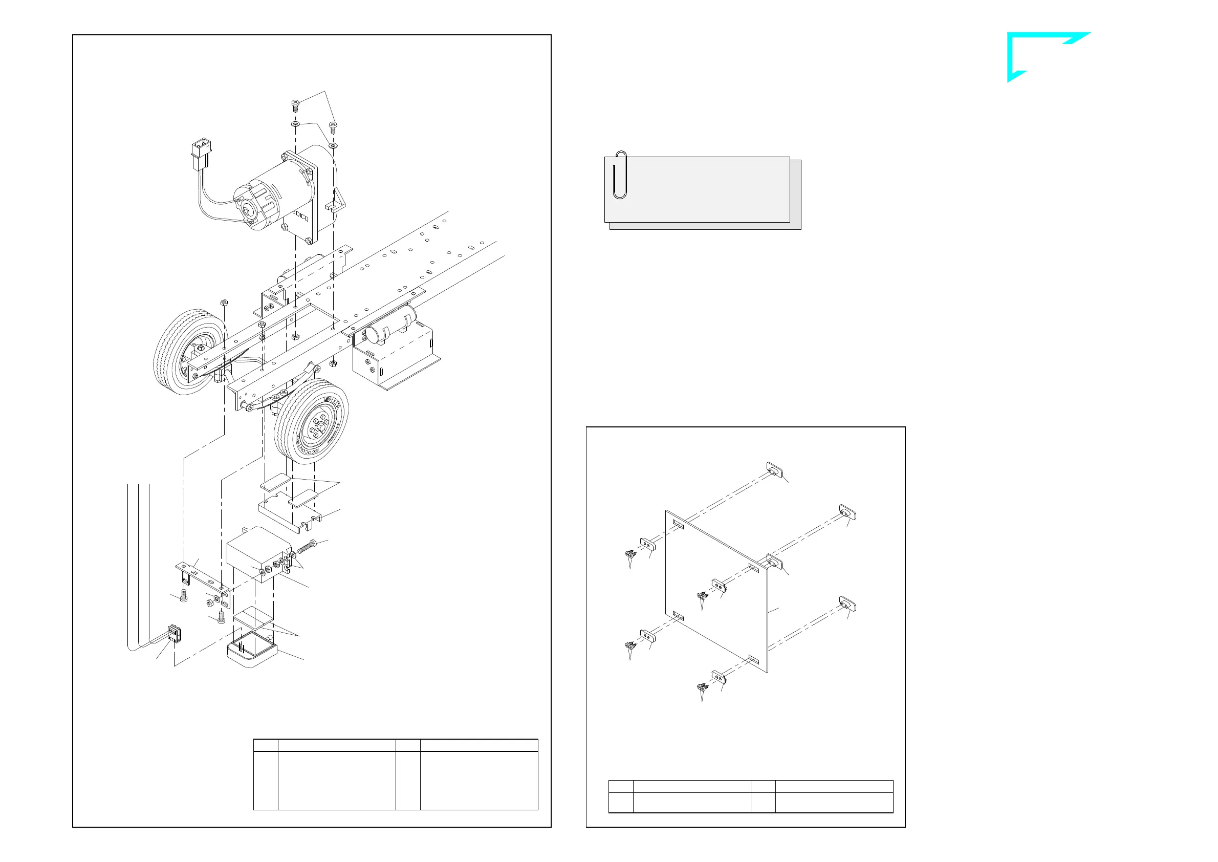
Once assembled, the gearbox is inserted from above into the ope-
ning in the frame and secured at the sides with screws 2, washers 13
and M3 nuts. At the same time the drive shaft 1048 (see ill. 15) is in-
serted at the joint balls between the gearbox and the differential.
16.2 Mounting the servo unit
Start by screwing on the servo supporting angle 760 underneath to
the frame; for this purpose use screws 2 and nuts M3. Accordingly to
the drawing add now two screws 4 with washers 13 and nuts M3 to
the steering servo. Finally use washers 13 and nuts M3 to fix the
complete unit onto the servo supporting angle.
16.3 Mounting the PCB support
Use two adhesive pads 655 to affix the PCB support 723 in front of
the gearbox under the frame.
16.4 Attaching the blinker switch
Attach the blinker switch with two adhesive pads 655 that way onto
the steering servo, that the clamp-type connector 929 lays in front of
the vertical leg of the frame tail piece (please refer to point 18.2).
NT ^ëëÉãÄäó=çÑ=íÜÉ=Å~Ä=êÉ~ê=é~åÉä=
Into the four slots of the rear panel 848 lay each one bar 849. From
inside press onto these outer bars each one bar 850; fix them with
screws 21.
41-e.DOC / K-Peter Page 8
Assembly of the cab rear panel ill. 17
Installation of drive unit and steerage ill. 16
steering servo
(not incl. in the kit)
the switch panel
fully assembled
blinker switch
Moment of torsion of the servo should
be at 20 Ncm. The servo supporting angle
will fit servos with the following data:
L x W x H:........................41 x 20 x 38 mm
Gauge for screwing ....................48 ±2 mm
Qty.
No. Assembly part
1
723
PCB support, small
1
760
Servo angle 1, small
1
929
Clamp-type connector, 3-
pole
Qty.
No. Assembly part
10
---
Nut M3
4
2
Screw M3 x 8
2
4
Screw M3 x 16
10
13
Washer 3.2
2
655
Adhesive pad, double-
sided
Qty.
No. Assembly part
4
849
Bar (outside), rear panel
4
850
Bar (inside), rear panel
Qty.
No. Assembly part
8
21
Tapping screw 2.2 x 4.5
1
848
Rear panel, Peterbilt
B-41-7
B-220-9


 To Next Page
 Loading...