Î
Connect the WEH
®
Connector to a suitable securing device (mechanical connection
via cylinder, rigid fixture, or other means) at the mounting bores “G” on the back of
the connector (or other secure fixture) so that the connector is securely connected
to the test piece when pressurized and can not come loose.
For the tightening torque, please refer to the table below.
Caution: The safety device must be designed to withstand the loosening force that
occurs (plus an appropriate safety tolerance).
Example of the loosening force: The test piece has an inner diameter of
1/2” (= 12.7 mm) and is tested at a maximum of 5 bar.
Loosening force* = pressure x area 0.5 N/mm
2
x 12.7
2
x n : 4 = 63.33 N (without
consideration of friction forces)
7�2 Installation of media line and pilot pressure line
Please note: Subsequent mentions of descriptions and position numbers refer to
Chapter 3. Product overview / product description on page 10.
Î
Unscrew the protection caps from the connection ports.
Î
Clamp the WEH
®
Connector in a vice with aluminium clamping jaws to mount the
media line and pilot pressure line.
Note: The WEH
®
Connector must not be damaged during clamping.
Î
Screw the pilot pressure port ‘P1’ pressure-tight onto the connection port of the pilot
pressure line.
For the tightening torque, please refer to the table below.
Î
Screw the ‘B1’ media inlet pressure-tight to the port for the media line.
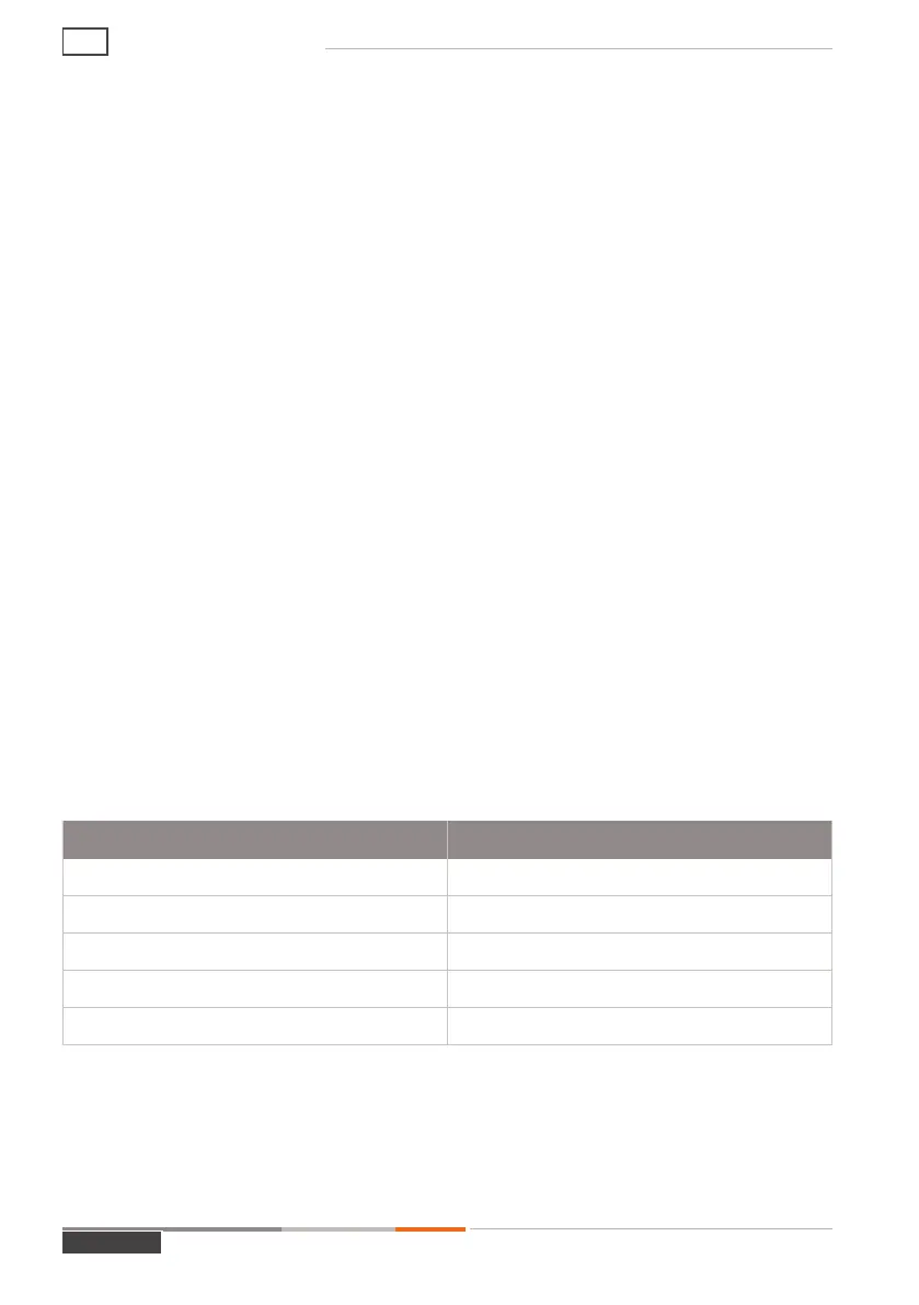
For the tightening torque, please refer to the table below.
Ports Torque
M5 5 Nm ± 2 Nm
M6 6 Nm ± 2 Nm
G1/8“ female thread 10 Nm ± 2 Nm
G1/2“ female thread 50 Nm ± 2 Nm
G3/4" female thread 60 Nm ± 2 Nm
Î
Please note the connection size marked on your product.
- Other connection sizes are available on request.
MD-10187-L51-R1.3.0-03
Page 18
Operating instructions
AE