WP13 Diesel Engine Series Operating Manual
15
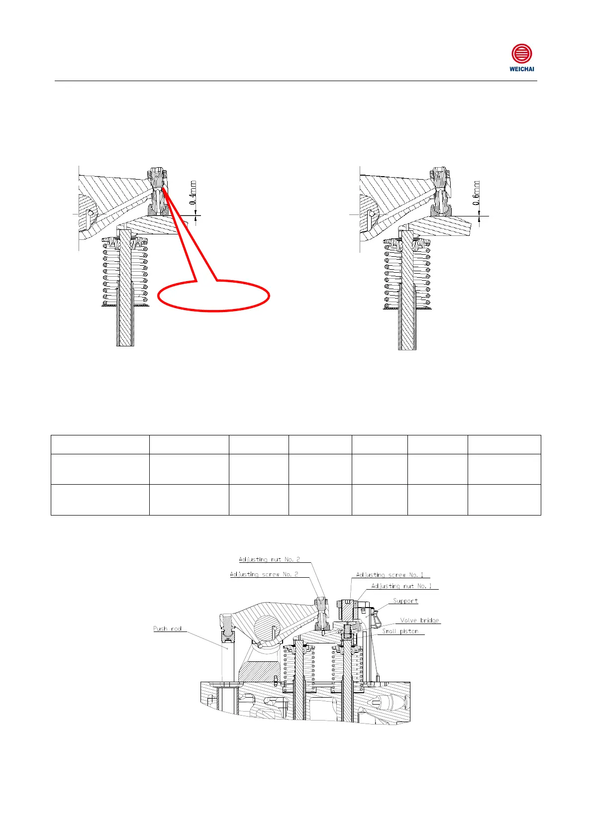
C. As shown in Table 3-1, use a feeler to check the clearance between the upper surface of the
valve axle and the valve rocker arm. The WP13 diesel engine should have its intake and
exhaust valve clearance of 0.4mm and 0.6mm respectively as required. If a too large or too
small clearance exists, you can adjust the adjusting bolt on the rocker arm to meet the
above-mentioned clearance requirements, as shown in Figure 5-13;
Adjusting bolt
Intake valve clearance in the cold state 0.4mm Exhaust valve clearance in the cold state 0.6mm
Figure 5-13
D. After Cylinder 1 or Cylinder 6 has been checked, turn the crankshaft forward 360° to have
Cylinder 6 or Cylinder 1 at its working stroke, then check and adjust the remaining valves.
Table 5-1
Cylinder 1 Cylinder 2
Cylinder 3 Cylinder 4
Cylinder 5
Cylinder 6
Cylinder 1
compression stroke
Intake and
exhaust valves
Intake
valve
Exhaust
valve
Intake
valve
Exhaust
valve
Unable to be
adjusted
Cylinder 6
compression stroke
Unable to be
adjusted
Exhaust
valve
Intake valve
Exhaust
valve
Intake
valve
Intake and
exhaust valves
For such exhaust valve with an EVB auxiliary braking device, its clearance can be adjusted as
follows:
Figure 5-14 Exhaust Valve and EVB Clearance Adjustment
A. The piston is at the compression TDC;
 Loading...