6
1
56
3
5
51
51
14
1
27
4
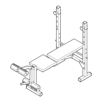
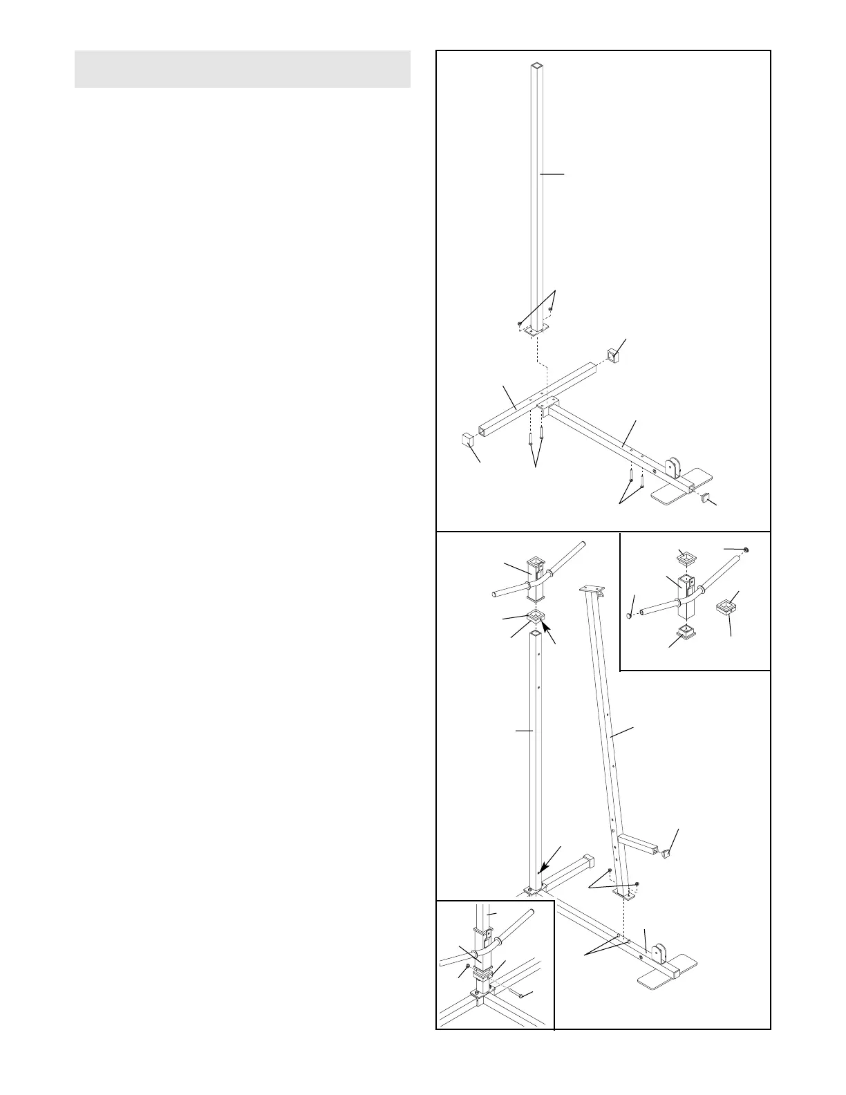
1. Before beginning assembly, be sure that you
have read and understand the information in
the box on the previous page.
Press a 2” Square Outer Cap (51) onto each end
of the Stabilizer (5). Press a 2” Square Inner Cap
(27) into the end of the Base (4).
Insert two 5/16” x 2 3/4” Carriage Bolts (14) up
through the Stabilizer (5). Insert two 5/16” x 2 1/2”
Carriage Bolts (1) up through the Base (4).
Slide the bracket end of the Base (4) onto the
5/16” x 2 3/4” Carriage Bolts (14) in the Stabilizer
(5). Slide the Rear Upright (56) onto the Carriage
Bolts. Hand tighten a 5/16” Nylon Locknut (3)
onto each Carriage Bolt.
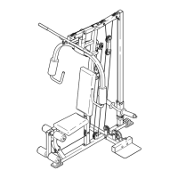
FRAME ASSEMBLY
2. Refer to drawing 2a. Press a 1” Inner Cap (61)
into each end of the weight tube on the Weight
Carriage (19). Note: The Square Slider Bushings
(70) should be pre-assembled to the Weight
Carriage and Weight Stop (67).
Turn the Weight Stop (67) so that the hole in the
Weight Stop is oriented in the same direction as
the hole in the bottom of the Rear Upright (56).
Make sure that the Square Slider Bushing (70)
is above the Weight Stop. Slide the Weight Stop
onto the Rear Upright.
Refer to drawing 2b. Secure the Weight Stop
(67) to the hole near the base of the Rear Upright
(56) with a 5/16” x 2 3/4” Bolt (11) and a 5/16”
Nylon Jamnut (72). Slide the Weight Carriage
(19) onto the Rear Upright.
Press a 1” Square Inner Cap (65) into the Front
Upright (42). Slide the Front Upright onto the
5/16” x 2 1/2” Carriage Bolts (1) in the Base (4).
Hand tighten a 5/16” Nylon Locknut (3) onto each
Carriage Bolt. Do not tighten the Nylon
Locknuts yet.
2
42
67
70
19
56
Hole
Hole
65
3
1
4
70
70
67
19
61
61
70
2a
2b
72
19
11
67
56