24
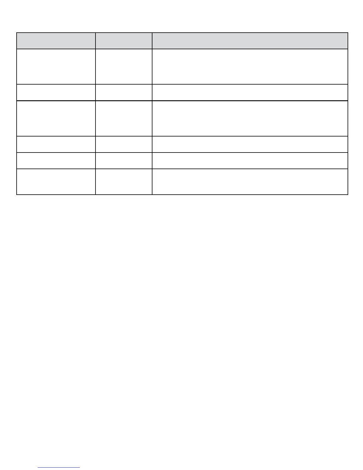
Input Calibration points
Range Values Notes
Volts/Thermocouple 10 mV, 20 mV,
50 mV, 80 mV,
200 mV, 1 V
If the internal switches are set to 10 V, you must supply
a signal ten times the displayed value, e.g. 10 V for the
1V point.
mA 20 mA
RTD/Resistance
100 Ω, 200 Ω,
500 Ω, 800 Ω,
2 kΩ, 10 kΩ
Use four wire mode
Individual calibration As selected Allows you to recalibrate any of the points above
Fine adjust Current input Fine tune the adjustment for the range you have selected.
All All ranges Complete calibration of all points. Internal switches must
be in the 1V position.
Input calibration
1. Save the current calibration to disk (select ‘Save Calibration data’
from the ‘Device’ menu).
2. Select ‘Calibrate Input’ from the ‘Device’ menu.
3. E
nter the calibration password (Default is 101).
4. Choose the calibration required (see Input calibration points table for
guidance).
5
. Supply the signals requested by the software and follow the
instructions on screen. Press the ‘Done’ button when finished.