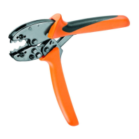
Description of device
A Insertion funnel G Crimping drum
B Conductor stop, adjustable, H Release opening
min. 3,5 – max. 13 mm I Control gate for selecting
C Adjusting screw ferrule size
D Cutting edge 0,5 mm
2
to 2,5 mm
2
E Hand lever J
Dial for adjusting cross-sectional area
F Grip flap
K
ferrule chain
Tool set-up
1
• Open grip flap F.
2
• Press the cross-section dial J.
3
• Turn in the direction of arrow and set to the proper ferrule size.
Then release the cross-section dial J.
Please note: In order to guarantee proper function, the cross-section dial (J)
must now be re-locked into place.
4 • Adjust control gate I to size of ferrule.
• This will ensure that the ferrule chain K runs properly.
5
• Insert the ferrule chain K flat into the guide of the enclosure, so that the first ferrule
lies in the crimping die of crimping drum G.
• Turn down the free end of the ferrule chain K as shown in Figure 5.
Close grip flap
F.
Cutting: flexible conductor with cross-sectional area (CSA) between
0.5 and 2.5 mm
2
6 Insert the conductor into the guide, and press hand lever E.
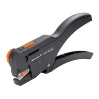
Insulation stripping: conductor with CSA between 0.5 and 2.5 mm
2
7 • Adjust variable conductor stop B to the length of insulation stripping.
For ferrules this is usually 10 mm.
8 • If necessary, use adjusting screw C to adjust the insulation stripping tool to the
insulation thickness required.
Crimping: wire end ferrules with CSA between 0.5 and 2.5 mm
2
9 •
Insert the stripped conductor straight into the ferrule through lateral opening
A
.
• Applying slight pressure, displace crimping drum
G
in the direction of the
conductor and keep under pressure.
• You will see that dial J is laterally displaced in the direction indicated by the
arrow. This will increase the distance from the enclosure.
• In this position, hand lever E must be pressed as far as it will go.
• The locking device then releases hand lever E so that it can be opened.
10 • Re-open hand lever E and remove the conductor with the crimped ferrule.
Modifying the tool for use with other cross-sectional areas
Open grip flap F, remove the ferrule strip, and continue as described under
“Tool set-up”.
Storage: store the tool only in open condition.
Replacing cutting edge
11 • Loosen the screw, and withdraw cutting edge D, screw and socket.
12 • Insert replacement cutting edge D, socket and screw, tighten screw.
Releasing the locking device
13 •
The tool has an automatic lock that ensures the desired crimping quality is
achieved.
The automatic lock is released using a screwdriver (release opening H)
8
en
 Loading...