EasyManua.ls Logo

weintek MT6071 Series - User Manual

weintek MT6071 Series
2 pages
Print Icon
To Next Page IconTo Next Page
Loading...
Installation and Startup Guide
This document covers the installation of MT6071/8071/8101iE Series HMI, for the detailed
specifications and operation, please refer to Brochure and EasyBuilder Pro User Manual.
Install Environment:
NEMA Rating
The HMI product is NEMA 4 rated (Indoor Only).
Electrical
Environment
The HMI product has been tested to conform to European CE requirements. This
means that the circuitry is designed to resist the effects of electrical noise. This
does not guarantee noise immunity in severe cases. Proper wire routing and
grounding will insure proper operation.
Environmental
Considerations
(1) Make sure that the displays are installed correctly and that the operating
limits are followed. Avoid installing units in environments where severe
mechanical vibration or shocks are present.
(2) Do not operate the unit in areas subject to explosion hazards due to
flammable gases, vapors or dusts. MT8071iE is certified in accordance with
ATEX zone 2/22 categories 3 G/D. The unit has to be installed in an
additional enclosure ensuring a minimal protection level for 3G/D
equipment. The enclosure equipped with the unit has to be certified and
shouldn’t be opened when an explosive atmosphere is present.
(3) Do not install the unit where acid gas, such as SO2 exists.
(4) This device should be mounted in the vertical position and for use on the flat
surface enclosure.
(5) Conform to UL508 (ISBN 0-7629-0404-6) machine safety for use in
Pollution Degree 2 Environment.
(6) Relative Humidity: 10% ~ 90% (non-condensing)
Unpacking the Unit
Unpack and check the delivery. If damage is found, notify the supplier.
NOTE:
Place the operator panel on a stable surface during installation. Dropping it or letting it fall may
cause damage.
(1) Installation Instruction, 2-sided A4 *1
(2) Human Machine Interface *1
(3) Power Connector *1
(4) Brackets & Screws *1 pack
(5) USB Stick Clamp & Tying Strap *1
(6) Fuse 1.25A/250V 5*20mm *1
Installation Instructions
Secure the operator panel in position, using all the fastening holes and the provided brackets
and screws. Screw Torque: 2.6 ~ 3.9 lbf.in. (For reaching waterproof effect and preventing the panel
from being deformed.)
Type
A(mm)
B(mm)
MT6071/8071iE
192
138
MT8101iE
260
202
USB Stick Clamp Usage
Combining the USB Stick with the clamp and the tying strap can prevent USB stick from disconnecting
with HMI when strong vibration is present.
1. Insert the USB connector to the clamp and tie them together with the tying strap.
2. Press the spring and insert the USB stick into HMI.
Power Connections
NOTE:
1. Connect positive DC line to the ‘+’ terminal and
the DC ground to the ‘- terminal.
2. When downloading project using a USB cable,
do not connect HMI with PLC and PC
simultaneously, for electric potential difference
may result in damage to HMI or PC.
System Settings
When HMI is powered up and displays image,
click the system setting button.
(Default System Password: 111111)
It is necessary to connect the HMI to
your network through a RJ-45 cable.
(N/A for MT6071iE)
MT6071/8071/8101iE series
Installation Instruction
Go to the Network tab, you may choose
to auto get DHCP IP, or designate your
own IP.
(B)
Cutout
3
5
4
1
2
Question and Answer IconNeed help?

Do you have a question about the weintek MT6071 Series and is the answer not in the manual?

Summary

Installation and Startup Guide

Environmental Considerations

Avoid extreme environments, explosion hazards, acid gas, and ensure vertical mounting. Relative humidity 10-90%.

Installation Procedure

Secure panel using provided brackets and screws. Torque spec: 2.6-3.9 lbf.in for waterproofing.

Power Connection Guidelines

Connect DC lines to terminals. Avoid simultaneous PLC/PC connection during USB download.

System Settings Configuration

Access system settings, connect via RJ-45, configure IP (DHCP/static).

EasyBuilder Pro Software Settings

Software Download Process

Use F7 to open download dialog, select Ethernet/IP, enter IP, and download project. Use USB for MT6071iE.

Safety and Operational Warnings

Power Supply Requirements

Unit requires 24VDC (±20%). Peak current up to 2A. Internal fuse protects against polarity errors.

Overview

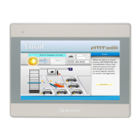
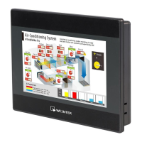
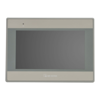
This document provides installation and operational guidelines for the MT6071/8071/8101iE Series Human Machine Interface (HMI). It covers essential aspects from initial setup to advanced system configurations and safety considerations.

Function Description

The MT6071/8071/8101iE Series HMI serves as an interface for controlling and monitoring industrial processes. It is designed to resist electrical noise and conform to European CE requirements, ensuring reliable operation in various industrial environments. The device supports communication with controllers via multiple interfaces, including RS232 and RS485, and can be integrated into a network via an RJ-45 cable (for MT8071iE and MT8101iE models). The HMI allows users to download project files, configure system settings, and perform touch screen calibration.

Important Technical Specifications

  • NEMA Rating: NEMA 4 rated (Indoor Only), indicating protection against dust and splashing water.
  • Cutout Dimensions:
    • MT6071/8071iE: A=192mm, B=138mm
    • MT8101iE: A=260mm, B=202mm
  • Power Supply: DC power only, voltage range 24±20% Volts DC. The peak starting current can be as high as 2A.
  • Environmental Considerations:
    • Operating limits must be followed, avoiding severe mechanical vibration or shocks.
    • Not for use in areas subject to explosion hazards due to flammable gases, vapors, or dusts, unless specifically certified (MT8071iE is ATEX zone 2/22 certified for categories 3 G/D, requiring installation in an additional enclosure).
    • Avoid installation where acid gas (e.g., SO2) exists.
    • Mounting: Vertical position on a flat surface enclosure.
    • Conforms to UL508 machine safety for Pollution Degree 2 Environment.
    • Relative Humidity: 10% ~ 90% (non-condensing).
  • Communication Interfaces:
    • COM1: RS232 (9 Pin, Male, D-sub)
    • COM2/COM3: RS485 (9 Pin, Female, D-sub). COM2 and COM3 RS485 2W support MPI 187.5K (use one at a time).
  • Fusing: Internal fuse prevents damage from overcurrent conditions. DC voltage sources should provide proper isolation from main AC power.
  • Wire Routing: Power wire length should be minimized (Max: 500m shielded, 300m unshielded). Twisted pair cables are recommended for power and signal wires. Surge suppression devices are advised for lightning or surges. AC, high energy, and rapidly switching DC power wiring should be separated from signal wires. A resistor and capacitor (1M Ohm and 4700pF) in parallel connection between the ungrounded DC power supply and the frame ground are recommended for static and high frequency dissipation.

Usage Features

  • Installation: Secure the operator panel using fastening holes and provided brackets/screws with a torque of 2.6 ~ 3.9 lbf.in for waterproof effect and to prevent panel deformation.
  • USB Stick Clamp Usage: A clamp and tying strap are provided to secure the USB stick, preventing disconnection during strong vibrations.
  • Power Connections: Connect positive DC line to the '+' terminal and DC ground to the '-' terminal. Avoid connecting HMI with PLC and PC simultaneously via USB cable during project download to prevent damage from electric potential difference.
  • System Settings: Access system settings by clicking the system setting button upon power-up (default password: 111111). Network configuration (for MT8071iE/MT8101iE) allows for DHCP IP acquisition or manual IP designation.
  • Software Configuration (EasyBuilder Pro):
    • Download project files via Ethernet (by entering HMI IP) or USB cable (for MT6071iE).
    • Screensaver and backlight saver are recommended to prevent image persistence.
  • DIP Switch Settings: Four DIP switches (SW1-SW4) allow configuration of various modes:
    • Touch Screen Calibration Mode (SW1 ON, SW2 OFF, SW3 OFF, SW4 OFF)
    • Hide HMI System Setting Bar (SW1 ON, SW2 ON, SW3 OFF, SW4 OFF)
    • Boot Loader Mode (SW1 OFF, SW2 OFF, SW3 ON, SW4 OFF)
    • Not supported (SW1 OFF, SW2 ON, SW3 OFF, SW4 OFF)
    • Normal (SW1 OFF, SW2 OFF, SW3 OFF, SW4 OFF)
    • Alternatively, touch screen calibration can be entered by pressing and holding anywhere on the screen for more than 2 seconds at HMI startup.

Maintenance Features

  • Unpacking and Inspection: Upon delivery, unpack the unit and check for damage. Notify the supplier if any damage is found. Place the panel on a stable surface during installation to prevent damage.
  • Battery Replacement: Battery replacement must be performed by qualified personnel, with care taken when handling lithium batteries.
  • Troubleshooting: If the display does not come on within 5 seconds of power up, remove power and check wiring for proper connections before powering up again.
  • Safety Recommendations:
    • A hard-wired EMERGENCY STOP should be fitted in any system using HMI.
    • Do not power the unit and inductive DC loads, or input circuitry to the controller, with the same power supply.
    • System designers must be aware of potential device failures and electrical interference that could lead to unsafe conditions. Appropriate precautions and programming checks (e.g., limit checks for writable registers controlling critical parts) are necessary to ensure safety.

Limited Warranty

The product is warranted against defects in design and manufacture. Defective products will be repaired or replaced at Weintek's discretion. The warranty period is 12 months from the manufacturing month. It does not cover damage caused by Force Majeure, accident, negligence, improper installation or misuse, repairs by unauthorized technicians, or products with removed/damaged identification markings.

weintek MT6071 Series Specifications

General IconGeneral
Brandweintek
ModelMT6071 Series
CategoryControl Panel
LanguageEnglish

Related product manuals