EasyManua.ls Logo

weintek MT8121XE Series - User Manual

weintek MT8121XE Series
2 pages
Print Icon
To Next Page IconTo Next Page
Loading...
Installation and Startup Guide
This document covers the installation of MT8121/8150XE Series HMI, for the detailed specifications
and operation, please refer to Brochure and EasyBuilder Pro User Manual.
Install Environment:
NEMA Rating
MT8121/8150XE Series HMI is NEMA 4 rated (Indoor Use Only).
Electrical
Environment
MT8121/8150XE Series has been tested to conform to European CE
requirements. This means that the circuitry is designed to resist the effects of
electrical noise. This does not guarantee noise immunity in severe cases. Proper
wire routing and grounding will insure proper operation.
Environmental
Considerations
(1) Make sure that the displays are installed correctly and that the operating
limits are followed. Avoid installing units in environments where severe
mechanical vibration or shocks are present.
(2) Do not operate the unit in areas subject to explosion hazards due to
flammable gases, vapors or dusts. MT8150XE is certified in accordance
with ATEX zone 2/22 categories 3 G/D. The unit has to be installed in an
additional enclosure ensuring a minimal protection level for 3G/D
equipment. The enclosure equipped with the unit has to be certified and
shouldn‟t be opened when an explosive atmosphere is present.
(3) Do not install the unit where acid gas, such as SO2 exists.
(4) This device should be mounted in the vertical position and for use on the flat
surface enclosure.
(5) Conform to UL508 (ISBN 0-7629-0404-6) machine safety for use in
Pollution Degree 2 Environment.
Unpacking the Unit
Unpack and check the delivery. If damage is found,
notify the supplier.
Installation Instructions
Secure the operator panel in position, using all the fastening holes and the provided brackets
and screws. Screw Torque: 2.6 ~ 3.9 lbf.in. (For reaching waterproof effect and preventing the panel
from being deformed.)
Type
A(mm)
B(mm)
MT8121XE
305
231
MT8150XE
352
279
Power Connections
System Settings
When HMI is powered up and displays image,
press the system setting button.
(Default System Password: 111111)
It is necessary to connect the HMI to
your network through a RJ-45 cable.
MT8121/8150XE series
Installation Instruction
NOTE:
Place the operator panel on a stable
surface during installation. Dropping it or
letting it fall may cause damage.
Go to the Network tab, you may choose
to auto get DHCP IP, or designate your
own IP.
(A)
(B)
Cutout
(1)
(2)
(5)
(4)
(3)
(1) Installation Instruction, 2-sided A4 *1
(2) Human Machine Interface *1
(3) Power Connector *1
(4) Brackets & Screws *1 pack
(5) Fuse 1.6A/250V 5*20mm *1
3
5
4
1
2
Question and Answer IconNeed help?

Do you have a question about the weintek MT8121XE Series and is the answer not in the manual?

Summary

Installation and Startup Guide

Install Environment

Details NEMA rating, electrical, and environmental considerations for proper installation.

Unpacking the Unit

Instructions on how to unpack and check the unit for damage.

Installation Instructions

Cutout Dimensions

Provides A and B dimensions for the cutout required for panel installation.

Power Connections

Power and PLC;PC Connection Notes

Notes on connecting DC power and avoiding simultaneous PLC/PC connections via USB.

System Settings

Network Configuration

Guides on accessing system settings to configure network IP via DHCP or static assignment.

EasyBuilder Pro Software Settings

Software Download Procedure

Steps to download a project file to the HMI using EasyBuilder Pro software.

Communication Connections

COM Port Pinouts

Details pinouts for RS232 and RS485 (2W/4W) COM ports for communication.

Calibration Mode

Touch Screen Calibration

Instructions on how to calibrate the touch screen via the display or startup.

Safety and Operational Warnings

Power, Fusing, and Voltage Cautions

Cautions regarding power supply, fusing, high voltage, and supply voltage conditions.

Wiring and Emergency Stop

Warnings about wire routing, emergency stop implementation, and signal separation.

Hardware and Programming Considerations

Notes on hardware failure risks and programming safety checks for control systems.

Limited Warranty Information

Warranty Terms and Conditions

Outlines the limited warranty period, exclusions, and conditions for product defects.

Overview

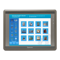
This document describes the installation and initial setup of the MT8121/8150XE Series Human Machine Interface (HMI) devices. These HMIs are designed for industrial applications, providing a user interface for controlling and monitoring machinery.

Function Description:

The MT8121/8150XE Series HMI serves as a control and monitoring interface for industrial systems. It allows operators to interact with programmable control systems, display operational data, and manage machine functions. The device is designed to be panel-mounted and offers connectivity options for various industrial communication protocols. It supports project downloads from a PC using EasyBuilder Pro software, enabling customized user interfaces and control logic. The HMI also features a touch screen for intuitive operation and includes calibration capabilities to ensure accurate touch response.

Important Technical Specifications:

  • NEMA Rating: NEMA 4 rated (Indoor Use Only), indicating protection against ingress of solid foreign objects (falling dirt, circulating dust, lint, fibers, and flyings) and water (splashing water, hose-directed water, and rain, sleet, snow).
  • Electrical Environment: Tested to conform to European CE requirements, indicating resistance to electrical noise. Proper wire routing and grounding are crucial for optimal operation.
  • Environmental Considerations:
    • Operating limits must be followed, avoiding severe mechanical vibration or shocks.
    • Not for operation in areas with explosion hazards due to flammable gases, vapors, or dusts, unless specifically certified. The MT8150XE model is ATEX zone 2/22 categories 3 G/D certified, requiring installation in an additional enclosure that ensures a minimal protection level for 3G/D equipment. The enclosure must be certified and not opened in an explosive atmosphere.
    • Avoid installation where acid gas (e.g., SO2) exists.
    • Must be mounted in a vertical position on a flat surface enclosure.
    • Conforms to UL508 (ISBN 0-7629-0404-6) machine safety for use in Pollution Degree 2 Environment.
  • Power Supply:
    • DC power only, voltage range: 24±20% Volts DC.
    • Compatible with most controller DC systems.
    • Internal switching power supply.
    • Peak starting current can be as high as 2A.
    • An internal fuse prevents damage from incorrect DC power polarity and overcurrent conditions, though it does not guarantee protection in all overcurrent scenarios. DC voltage sources should provide proper isolation from main AC power and similar hazards.
  • Power Connections:
    • Connect positive DC line to the '+' terminal and DC ground to the '-' terminal.
    • Avoid connecting HMI with PLC and PC simultaneously to prevent potential differences from destroying USB ports.
  • Communication Ports:
    • COM1 [RS232]: 9-pin Male D-sub, with RxD, TxD, and GND.
    • COM1/COM3 [RS485]: 9-pin Female D-sub, supporting 2-wire (Data-, Data+) and 4-wire (Rx-, Rx+, Tx-, Tx+) configurations. COM1 and COM3 RS485 2W support MPI 187.5K (use one at a time). Both COM1 and COM3 RS485 have isolation protection.
    • Ethernet: RJ-45 cable for network connection, supporting DHCP or designated static IP.
  • Physical Dimensions (Cutout):
    • MT8121XE: A(mm) 305, B(mm) 231
    • MT8150XE: A(mm) 352, B(mm) 279
  • Included Accessories: Installation Instruction, Human Machine Interface, Power Connector, Brackets & Screws (1 pack), Fuse 1.6A/250V 5*20mm (1).

Usage Features:

  • Installation:
    • Secure the operator panel using all fastening holes, provided brackets, and screws.
    • Recommended screw torque: 2.6 ~ 3.9 lbf.in. to ensure waterproof effect and prevent panel deformation.
    • Place the operator panel on a stable surface during installation to prevent damage from dropping.
  • Software Configuration (EasyBuilder Pro):
    • Requires EasyBuilder Pro version 4.00.01 or later.
    • Project files are downloaded to the HMI via Ethernet (using the HMI's IP address) or USB cable.
    • The software allows for customization of the user interface and control logic.
  • System Settings:
    • Accessed by pressing the system setting button when the HMI powers up and displays an image.
    • Default System Password: 111111.
    • Network settings (DHCP or static IP) are configured here.
  • Touch Screen Calibration:
    • Initiated by pressing the calibration mode button when the HMI powers up.
    • Alternatively, press and hold anywhere on the screen for more than 2 seconds when the HMI starts.
    • Follow on-screen prompts to touch "+" signs to calibrate the touch panel.
  • Safety Recommendations:
    • A hard-wired EMERGENCY STOP should be fitted in any system using HMI.
    • Do not power the unit and inductive DC loads, or input circuitry to the controller, with the same power supply.
    • The system designer must be aware of potential failures in controller systems that could lead to unsafe conditions. Electrical interference can cause equipment start-up. Appropriate precautions, including limit checks in the controller program for critical parts of plant/machinery, are necessary.

Maintenance Features:

  • Unpacking and Inspection: Upon delivery, unpack the unit and check for damage. Notify the supplier if any damage is found.
  • Wiring Guidelines:
    • Minimize power wire length (Max: 500m shielded, 300m unshielded).
    • Use twisted pair cables for power and signal wires, conforming to impedance matching.
    • Use appropriate surge suppression devices if wiring is exposed to lightning or surges.
    • Keep AC, high energy, and rapidly switching DC power wiring separated from signal wires.
    • Add a resistor and capacitor (1M Ohm and 4700pF) in parallel between the ungrounded DC power supply and the frame ground to dissipate static and high frequency.
  • Troubleshooting (Power Up): If the display does not come on within 5 seconds of power up, remove power. Check wiring for proper connections and try to power up again.
  • Limited Warranty:
    • Warrants against defects in design and manufacture for 12 months from the manufacturing month.
    • Does not cover damage from Force Majeure, accident, negligence, improper installation or misuse, repairs by unauthorized technicians, or products with removed/damaged identification markings.

weintek MT8121XE Series Specifications

General IconGeneral
Brandweintek
ModelMT8121XE Series
CategoryControl Unit
LanguageEnglish