INDEX: FAILURE / CAUSE
LS200 MECHANICAL
D E F I N I T I O N S
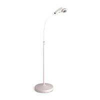
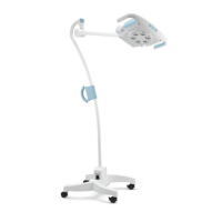
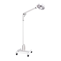
To simplify text, numbers are used for the names of the joints on the LS200. See figure 1 on
page 9. This page of information is for referencing the joints on the LS200 and giving a general
description of required adjustments. This page is not service instructions.
JOINT NUMBER: DESCRIPTION:
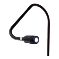
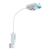
Yoke/Housing joint ..... The crescent shaped part is the yoke. It holds the
(# 1 joint) lamp housing. This is a technician adjustable
friction joint. Adjust friction to keep lamp housing
in position when moved. Tighten/loosen lamp
housing 15/16" nut on pivot bolt. (Secure this nut
with Loctite #242, M30338.) REMOVE flakes of
Loctite which may be in lamp housing. This is the
only joint that is lubricated (Dow Corning #7
release compound, M11175)
Yoke-arm joint .... The yoke is attached to the upper (long) (# 2 joint)
arm at the ‘yoke-arm’ joint # 2. (User can adjust
this friction joint by tightening or loosening slotted
set screw in arm near joint. This set screw is secured
with Loctite #222, M30375.) To replace components
of joint # 2, remove short arm. (See sect. I.)
Arm joint .... The two arm sections are joined at the adjustable
(# 3 joint) ‘arm’ joint. (User can adjust this friction joint by
tightening or loosening the black knob.) To replace
or repair it, you must remove the lower arm and
release spring tension. (See sect.J.)
Universal connector .... The lower (short) arm attaches to the mounting
(# 4 joint) option (pole or wall mount) at the ‘universal
connector’ joint. (User can adjust this friction joint
by tightening or loosening the slotted set screw in
the arm near this joint. Do not use Loctite on this set
screw.)
Mount arm joint .... The mount arm attaches to the wall mount bracket
(# 5 joint) at the ‘mount arm’ joint. This joint is not
adjustable. Disassembled by removing 3 cap screws
underneath wall mount bracket.
8
 Loading...