The Company, L.L.C. Oklahoma City, Oklahoma Tel: (405) 672-6660 Fax: (405) 672-6661
wellmarkco.com
© The WellMark Company • Litho USA • All registered trademarks are the property of their respective owners. • IOM-6900 090923
3
6900
Series
Adjust the Adjusting Screw/Nozzle upward toward the Nozzle Seat,
by loosening Jam Nut and turning Adjustment Screw clockwise
(when looking at the bottom of the unit) until Output Pressure Gauge
starts to indicate a reading (1-3 psi).
Open the vessel inlet and observe the rising liquid level. Once the
liquid reaches the Displacer fine adjustment of the control can be
made within the diameter range of the Displacer by adjusting the
Adjusting Screw up or down to actuate the diaphragm-operated
motor valve. Once the desired adjustments are complete, tighten the
Jam Nut, being very careful not to inadvertently disturb theAdjusting
Screw setting.
- Turn Adjusting Screw counter-
clockwise (moves Nozzle orifice away from actuator pad).
- Turn Adjusting Screw clockwise
(moves Nozzle orifice toward actuator pad).
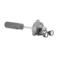
Normal pilot installation is (rise in liquid level resulting
from an increase of output). For (rise in liquid level
resulting in a decrease of output), simply loosen 3/4-16 Jam Nut
behind Pilot Head, and rotate Pilot Head 180° and re-tighten Jam Nut
(See Figure 3).
To INCREASE Liquid Level
To DECREASE Liquid Level
direct-acting
indirect-acting
Direct-Acting Indirect-Acting
Figure 3
Maintenance
The Series 6900 Cantilever Liquid Level Control requires very little
maintenance. As with any instrumentation, the most important
factors for long life and consistent operation is that supply pressure
be clean and dry.
From time to time the entire pilot head may come loose on the
Cantilever Rod. Check to assure that this connection is sound and
that the jam nut is properly tightened.
The flow of gas in the supply line will draw any foreign material or
particles as the gas moves to and through the control and valve.
Occasionally, this may result in a particle of sand, weld slag, etc.
becoming lodged in an orifice in theAdjusting Screw or Nozzle.
Shut off supply pressure to the control. Loosen the Jam Nut on the
bottom of the unit and unscrew the Adjusting Screw/Nozzle from the
Pilot Housing. Pull the Adjusting Screw/Nozzle completely free of
Clearing a Clogged Orifice
the Pilot Housing.
Remove O-Rings from Adjusting Screw. Clean Adjusting
Screw/Nozzle with solvent. Inspect for debris in orifices on side and
end of Nozzle, removing as necessary with thin gage wire. Care
should be exercised not to deform the orifice openings.
Inspect O-Rings for wear and replace if necessary. Lubricate O-
Rings with a light coating of general-purpose grease and reinstall on
the Nozzle. Take care that no grease clogs the orifices.
Gently re-insert the Adjusting Screw/Nozzle with O-Rings back into
the Pilot Housing, taking care not to damage the O-Rings in the
process. Readjust the Nozzle as directed on Page 2 under “Start
Up”. Once proper adjustment is made re-tighten the Jam Nut.
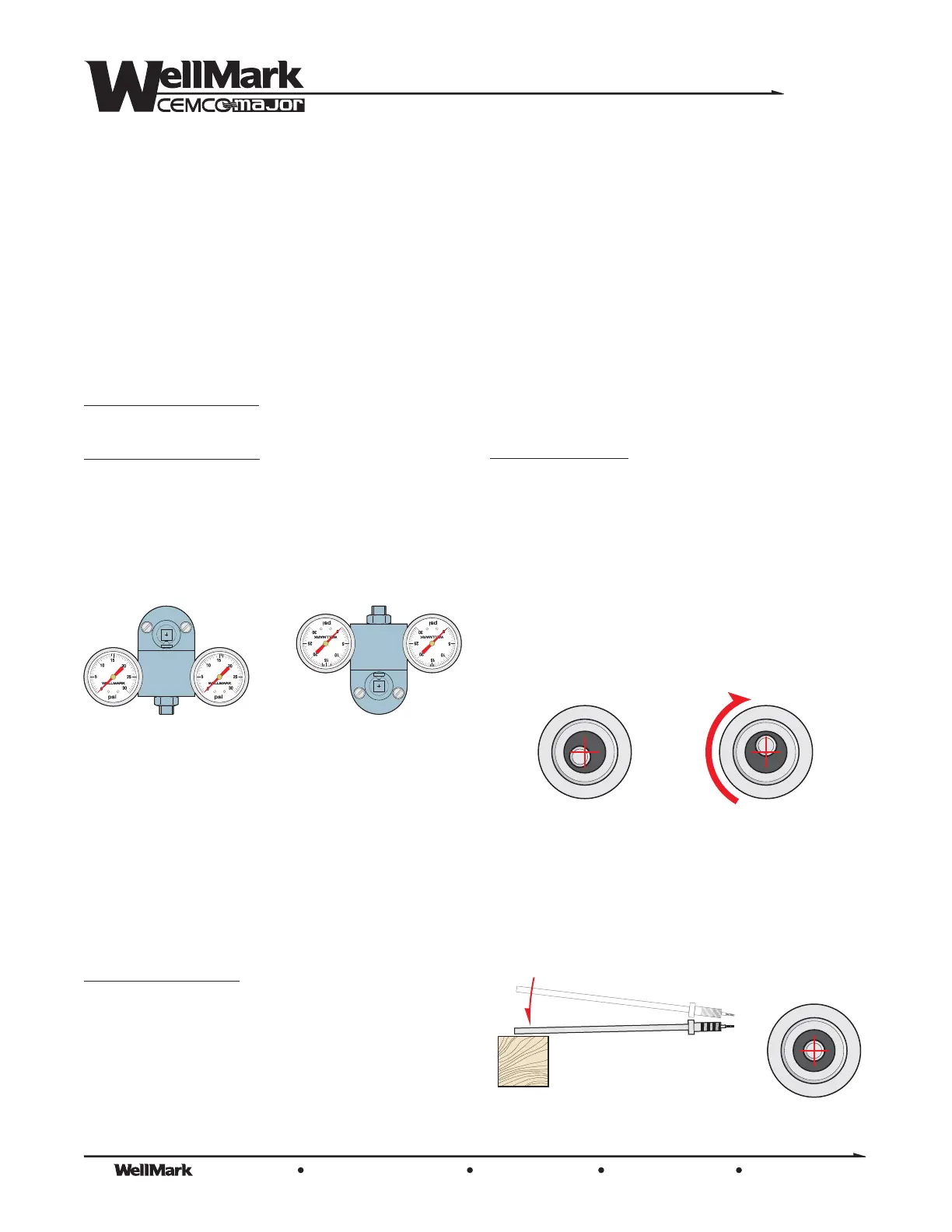
Occasionally, the Sensing Rod/Nozzle Seat will become misaligned
in the Sensing Rod Housing and must be re-alinged prior to
installation and use. This is a relatively easy procedure.
Once the unit is removed from service, remove the entire Rod
Assembly from the Pilot Head, detaching the Displacer as well.
Remove the Nozzle Seat by loosening the Hex Nut and pulling the
Nozzle Seat off the Sensing Rod. Peer into the end of the Rod
Assembly and note in which direction the Sensing Rod is off center.
Rotate the Rod Assembly such that the Sensing Rod offset is now in
the uppermost or 12-o’clock position (See Figure 4).
Centering Sensing Rod
Grasp the Rod Assembly by this end and lightly tap the opposite end
(the Displacer end) on a bench or block of wood. The Sensing Rod
will begin to move back into the center of the Sensing Rod Housing.
Continue with light taps until the Sensing Rod is properly centered
(Figure 5).
12 o’clock
Figure 4
Lightly tap
Correct
Alignment
Figure 5
 Loading...