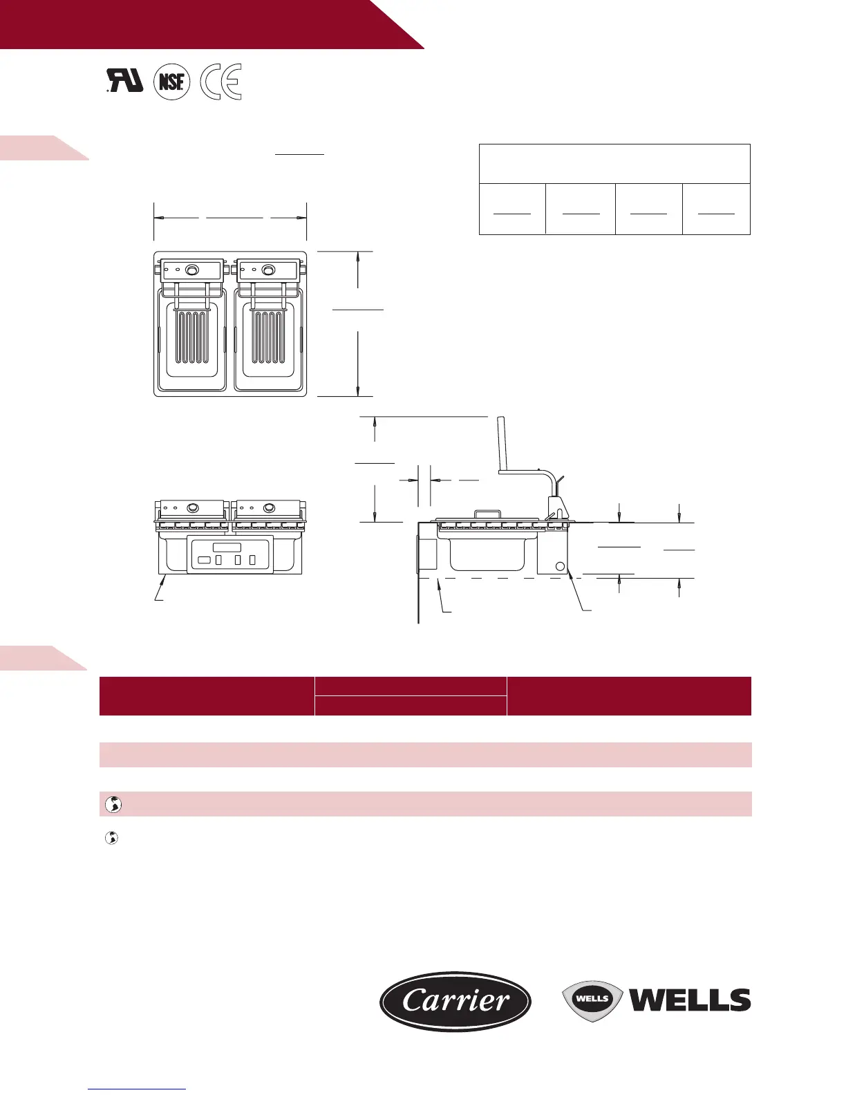
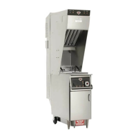
M O D E L
F - 8 5 6
B U I LT- I N F R Y E R
D I M E N S I O N S :
INCH
(MM)
W E L L S M A N U F A C T U R I N G
NOTE: Specifications are subject to change without notice. See installation instructions prior to installing the
unit. This document is not for installation purposes. The installation of recognized component units requires
additional evaluations to Underwriters Laboratories Inc. standards. Depending on the installation, clearances
can be changed upon further evaluations to UL standards.
THIS UNIT IS DESIGNED TO BE INSTALLED IN METAL COUNTERS ONLY
SUGGESTED CLEARANCE FROM
UNIT TO THE NEAREST SURFACE
BACK SIDE BOTTOM FRONT
2 1/4 3 6 3
(57) (76) (152) (76)
WELLS MANUFACTURING COMPANY
2 ERIK CIRCLE, PO BOX 280, VERDI, NV 89439 U.S.A.
USA PHONE: (775) 345-0444 • FAX: (775) 345-0569
FOR ORDERS ONLY: (888) 356-5362 • FAX: (800) 356-5142
www.wells-mfg.com
© 2002 WELLS MANUFACTURING • PRINTED IN THE U.S.A.
03/02 • REV(I) • PART NO. 37104
F - 8 5 6 E L E C T R I C A L S P E C I F I C AT I O N S :
F-856 W/STS 208 11500 31.9 31.9 31.9 NA NONE
F-856 W/STS 240 11500 27.6 27.6 27.6 NA 47.9 NONE
F-856 W/STS 480 11500 13.8 13.8 13.8 NA 24.0 NONE
F-856EU 380-415 11100 16 16 16 0 - NONE
Denotes export (EU) products.
MODELS VOLTS WATTS
AMPS PER LINE 3 PHASE
AMPS POWER
SINGLE PHASE SUPPLY CORD
L1 L2 L3 N
(229)
9
(214)
8 7/16
(435)
17 1/8
(51)
2
(598)
23 9/16
(630)
24 13/16
BOX
OUTLET
BOX
OUTLET
METAL SHIELD