PRECAUTIONS & GENERAL INFORMATION xi
SPECIFICATIONS 1
FEATURES & OPERATING CONTROLS 2
WIRING DIAGRAM 2
OPERATION 3
EXPLODED VIEW & PARTS LIST 4
1
This manual contains the information needed to properly service and repair this equipment.
TABLE OF CONTENTS
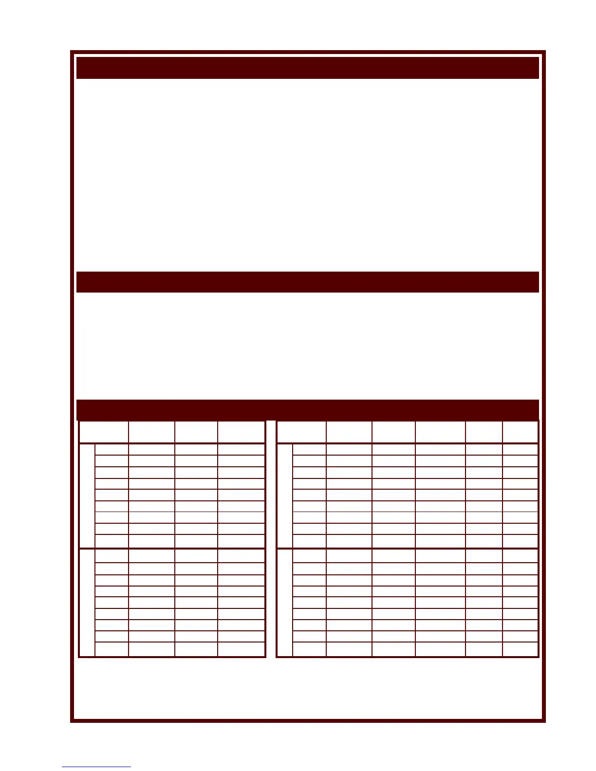
SPECIFICATIONS
INTRODUCTION
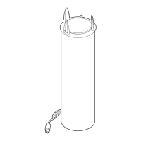
240V 1ø HEATED DROP-IN TUBES
MODEL DISH FLANGE REQ’D.
NO. DIA. DIA. CUTOUT*
UT4 UP TO 4” 7h ” 6d ” dia.
UT5 4d ”-5” 8h ” 7d ” dia.
UT57 5d ”-5H ” 9 ” 7d ” dia.
UT65 5L ”-6p ” 9H ” 8D ” dia.
UT7 6D ”-7h ” 10p ” 9l ” dia.
UT8 7L ”-8d ” 11L ” 10h ” dia.
UT9 8h ”-9d ” 12l ” 11h ” dia.
UT10 9h ”-10h ” 13l ” 12l ” dia.
UT12 10l ”-12” 15d ” 14d ” dia.
UTS4 UP TO 4” 7h ” 6j ” dia.
UTS5 4d ”-5” 8h ” 7n ” dia.
UTS57 5d ”-5H ” 9 ” 8f ” dia.
UTS65 5L ”-6p ” 9H ” 8D ” dia.
UTS7 6D ”-7h ” 10p ” 9F ” dia.
UTS8 7L ”-8d ” 11L ” 10B ” dia.
UTS9 8h ”-9d ” 12l ” 11B ” dia.
UTS10 9h ”-10h ” 13l ” 12B ” dia.
UTS12 10l ”-12” 15d ” 14j ” dia.
OPEN DROP-IN TUBES SHIELDED DROP-IN TUBES
MODEL DISH FLANGE REQ’D. WATTS AMPS
NO. DIA. DIA. CUTOUT*
UTH4 UP TO 4” 7h ” 6j ” dia. 240 2.0
UTH5 4d ”-5” 8h ” 7n ” dia. 240 2.0
UTH57 5d ”-5H ” 9 ” 8f ” dia. 240 2.0
UTH65 5L ”-6p ” 9H ” 8D ” dia. 300 2.5
UTH7 6D ”-7h ” 10p ” 9F ” dia. 300 2.5
UTH8 7L ”-8d ” 11L ” 10B ” dia. 300 2.5
UTH9 8h ”-9d ” 12l ” 11B ” dia. 300 2.5
UTH10 9h ”-10h ” 13l ” 12B ” dia. 500 4.2
UTH12 10l ”-12” 15d ” 14j ” dia. 500 4.2
UTY4 UP TO 4” 7h ” 6j ” dia. 240 1.0
UTY5 4d ”-5” 8h ” 7n ” dia. 240 1.0
UTY57 5d ”-5H ” 9 ” 8f ” dia. 240 1.0
UTY65 5L ”-6p ” 9H ” 8D ” dia. 300 1.3
UTY7 6D ”-7h ” 10p ” 9F ” dia. 300 1.3
UTY8 7L ”-8d ” 11L ” 10B ” dia. 300 1.3
UTY9 8h ”-9d ” 12l ” 11B ” dia. 300 1.3
UTY10 9h ”-10h ” 13l ” 12B ” dia. 500 2.1
UTY12 10l ”-12” 15d ” 14j ” dia. 500 2.1
120V 1ø HEATED DROP-IN TUBES
* NOTE: Verify dimensions by referring to the Installation Instructions included with the dispenser.
For metric sizes refer to the Specification Sheet included with the dispenser.
UTH and UTY heated dispensers are shielded. UTS shielded dispensers are not heated.
 Loading...