- 7 -
Note:
Observe the colour coding:
• "White" CINCH plug to white
CINCH socket
• "Red" CINCH plug to red CINCH
socket
• "Yellow“ CINCH plug to yellow
CINCH socket.
Connect the SCART double adapter
(1() to the AV socket of your transmis-
sion source (e.g. SAT receiver).
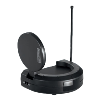
Adjusting the transmitter signals
The video transmitter (e) is designed
so that a suciently high output voltage
for faultless operation is supplied when
simultaneously connected to a source
(computer, DVD player, satellite receiver)
together with other devices via the in-
cluded adapter. The local TV switch (i) in
the connection panel is then in the "YES"
position.
If only the video transmitter (e) is con-
nected to the video source, without
another device such as a DVD player/
VCR), image disruptions may occur for
some device combinations. In this case,
set the slider switch (i) to "NO" (= no
additional device connected). This lowers
the signal power so that the video and
sound are transmitted without distortions.
Note:
If the AV socket of your transmission
source is already in use, use the out-
put of the SCART double adapter (1()
for the original connection . Connect
the infrared cable (2#) to the infrared
connection socket (u) of the trans-
mitter. Tape one of the self-adhesive
transmission diodes of the infrared
cable (2#) to the infrared receiver of
your transmission source.
Note:
Avoid attaching the transmission
diode directly to the infrared receiver
of your transmission source. Direct
remote control commands can now
be issued as usual.
Note:
Use the remaining transmission diodes
for additional devices. You can then
connect these devices with the trans-
mission source. Connect the transmitter
(e) with a connector power pack (2@)
using the 6 V DC connection socket (t).
Connect the connector power pack (2@)
with a 230 V
~
/ 50 Hz wall socket.
Use the "ON/OFF" switch (r), which
is located on the side, to switch on the
transmitter (e). Rotate the antenna for
the remote control signals (q) upward.
Orient the audio/video transmitter an-
tenna (a).
Important!
The unlabelled side must point in the
direction of the receiver (f).
Switch on your transmission source. If
necessary, start playback on your trans-
mission source (e.g. SAT receiver/set top
box, DVD/CD player, VCR, PC etc.).
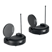
Connecting the receiver
Connect the other CINCH (RCA) cable
(2!) to the receiver (f) and the SCART-
CINCH adapter (2)).
Note:
Be sure to match the colours correctly.