EMS bus interface board manual
Current board version: 0.9 - April 2018 – Last document update 11 April 2019.
Please see the Github repository for all the details about working with the EMS bus.
https://github.com/bbqkees/Nefit-Buderus-EMS-bus-Arduino-Domoticz
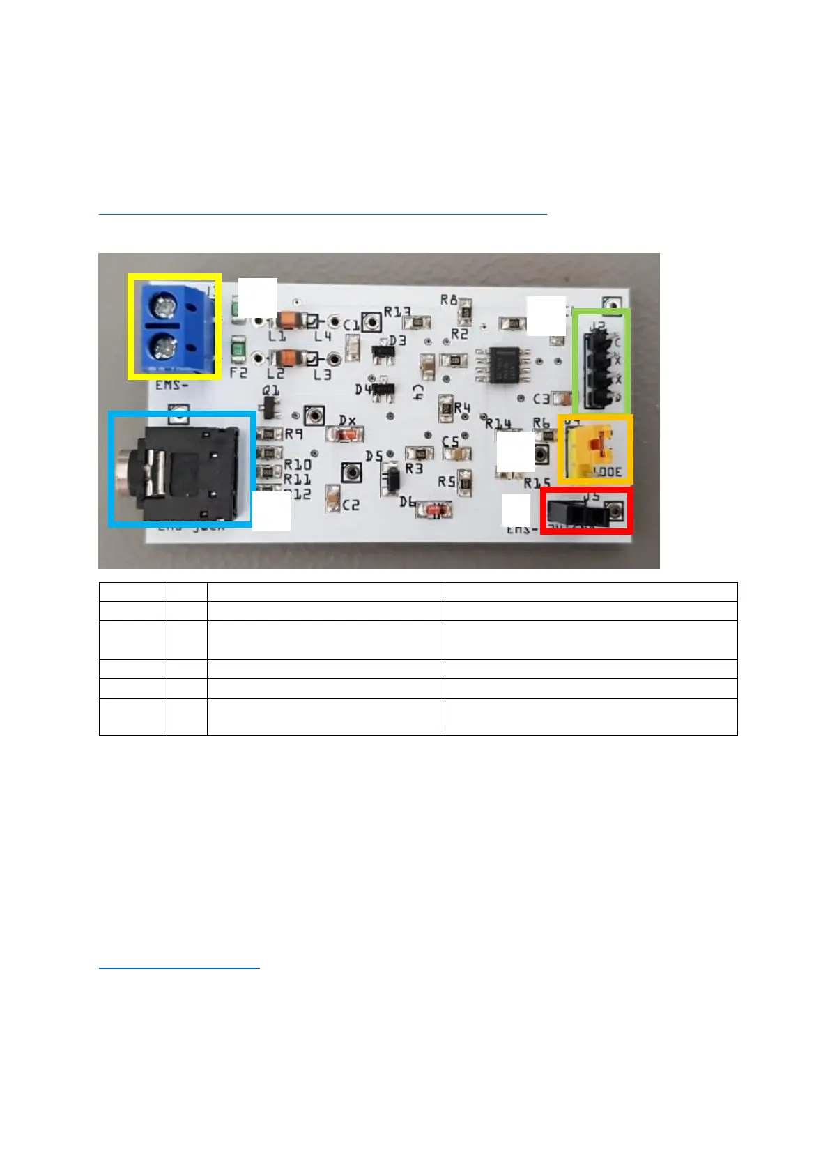
Connectors on the board
Polarity does not matter.
VCC/TX/RX/GND. Input 5V or 3.3V from
controller.
Only connect either J1 or J3.
RX resistor selector jumper
Select either 4k7 or 100E resistor.
8~16V pin from EMS service jack
Left pin EMS 8~16V DC. right pin GND. Max
power draw 200mA cont.
Before shipment, this board has been fully tested on my own boiler with an Arduino in RX and TX
mode on both 3.3V and 5V, and with both resistor settings. So the board you received works as
intended.
Keep this in mind when you created something with this board and it does not work. Do not
immediately assume the board is faulty. The most likely problems are in your own code or in the
connections to the microcontroller board. First try my Github examples to verify the board is working
in your setup and everything is wired up correctly.
If you have a persistent problem with the board you can always send an email to
bbqkees+pcb@gmail.com
In any case do not open a Paypal dispute.
 Loading...