EasyManua.ls Logo

Wemos D1 Mini V3 User Manual

Wemos D1 Mini V3
4 pages
To Next Page IconTo Next Page
Page #1 background imageLoading...
Page #1 background image
Wemos connections to the EMS board
The Wemos D1 Mini versions all have the same pinout, however the text on the board may vary
slightly. Below two examples.
Wemos D1 Mini V3 Wemos D1 Mini V2
Pin EMS board
Wemos pin
VC
3V3 (NOT 5V!!)
TX
D8
RX
D7
GD
G or GND
The Wemos, if purchased from me, comes pre-loaded with a stable firmware version from
https://github.com/proddy/EMS-ESP. I dont provide detailed support for the firmware itself as it is
not my own. Please READ the documentation on the repository very carefully.
When you power up the Wemos, it will start in Access Point (AP) mode. Connect via WiFi to the SSID
EMS-ESP and telnet to 192.168.4.1. (f.i. Putty is a simple program to use Telnet with). Then use the
set wifi command to configure your own network settings like set set wifi_ssid and set
wifi_password.
Alternatively connect the ESP8266 to your PC and open a Serial monitor to configure the settings.
Make sure you disable Serial support before connecting the EMS lines using set serial off.
Play around in the Telnet session with the available settings to make sure the Wemos can read and
write correctly to the EMS bus. The next step is integrating it into your home automation system. For
Home Assistant there is a full set of YAML configuration files available and for Domoticz there is a
first version of a python plugin available. You can find both in the ‘doc’ folder of the repository.
For Domoticz you also need to install a MQTT server/broker like Mosquitto.
If you dont know what this all means, please Google around and check the HA or Domoticz forum for
support on this.
Its also a good idea to give the Wemos a fixed IP address (also called a DHCP reservation) so your
home automation system can always find the Wemos even after reboots etc. You need to set this in
your router.
Take special care when upgrading the firmware on the Wemos. Read the complete Readme file on the
repository so you know exactly what you are doing otherwise you may brick the ESP!
VC
TX
RX
GD
VC
TX
RX
GD
After you connected the 4 wires as instructed
above, you can plugin a USB cable to the
Wemos to power it all up.
Question and Answer IconNeed help?

Do you have a question about the Wemos D1 Mini V3 and is the answer not in the manual?

Wemos D1 Mini V3 Specifications

General IconGeneral
MicrocontrollerESP8266
Operating Voltage3.3V
Digital I/O Pins11
Analog Input Pins1
Flash Memory4MB
Wi-Fi Standard802.11 b/g/n
Dimensions34.2mm x 25.6mm
Clock Speed80 MHz
USB InterfaceMicro USB
SRAM64KB
Analog Input Voltage (Max)3.3V

Summary

Wemos Connections to EMS Board

Wemos D1 Mini Pinout Examples

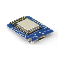
Illustrates pinout differences between Wemos D1 Mini V3 and V2 for EMS board connection.

Firmware and Initial Configuration

Details on Wemos firmware, WiFi AP mode, and initial Telnet configuration for network settings.

Home Automation Integration

Guidance on integrating with Home Assistant or Domoticz, including MQTT setup.

EMS Bus Interface Board Connectors

Board Connector Identification

Details the function and remarks for each connector (J1-J5) on the EMS bus interface board.

Troubleshooting and Support

Advice on common issues, board testing, and contact information for persistent problems.

Connecting to Controller and Voltage Considerations

Controller Connection and UART Settings

Guides connecting to Arduino/ESP8266/Pi via UART, including voltage levels and jumper selection.

Power Output and Safety Precautions

Details using header 5 for power, polyfuses, and essential safety warnings to prevent damage.

Connecting to the EMS Bus

Bus Connection Options

Explains using either the EMS bus service jack or the screw terminal for bus connection.

Reference Repository

Provides a link to the GitHub repository as a general starting point for EMS bus projects.