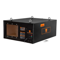
10. Remove the PCB and housing from the rear of the control panel. Refer to Figures 8 and 9 below.
Using the cutting pliers, carefully cut only the zip tie that secures the radio antenna to the housing.
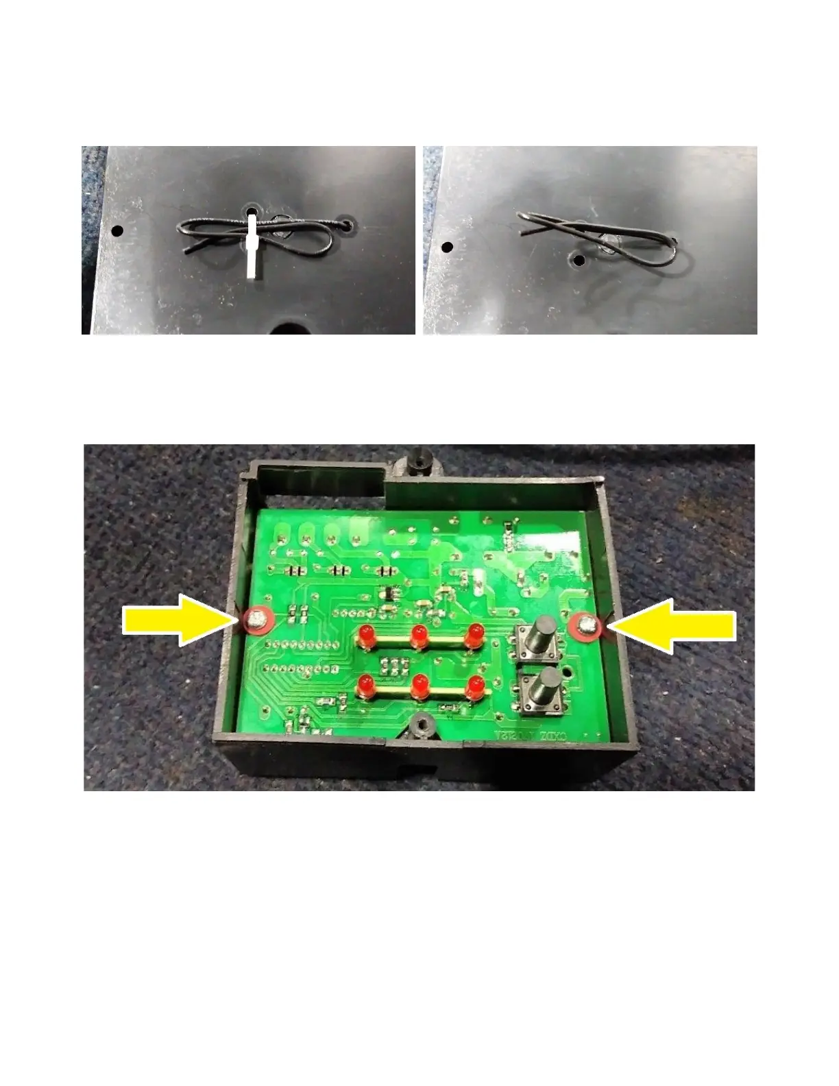
11. Flip the housing over. Using the Phillips head screw, remove the two screws indicated by yellow
arrows in Figure 10 below. Lift out the PCB.
12. Replace the old PCB with the new PCB. If applicable, make sure the radio antenna goes through
the hole in the back of the housing. You may choose to secure it with a zip tie if desired, but this is not
required.
13. Re-assemble the unit by following the above steps in reverse order. Press the label that was
removed in step 9 back into its original location. When re-assembling the grounding wire and
grounding bolt (refer to steps 4 & 5, Figures 3 & 4), assemble it in the order shown in Figure 11 below
(from left: nut, locking washer, flat washer, grounding wire, serrated washer, housing, bolt).
Figure 8: Cut the zip tie.
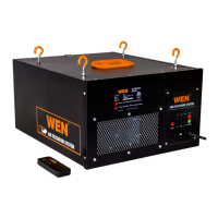
Figure 9: Zip tie has been cut.
Figure 10: Remove these two screws.
 Loading...