OPERATION
CONNECTING TWO INVERTER GENERATORS
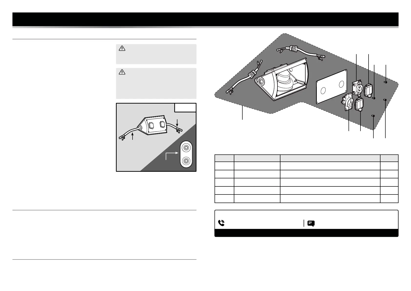
1. Place your parallel kit on a dry surface, such as dry
ground or the top of your generator.
2. The parallel kit has two sets of wires. Securely connect
each set of wires to each generator’s control panel. See
Fig. 1.
Insert the red plug into the red parallel connection port
and the black plug into the black port of each generator. If
the wires are not connected correctly, the generators will
not output any power.
Attach the green wire with metal ring to each generators’s
grounding nut.
NOTE: Failure to properly ground the generator or parallel
kit can increase your risk of electric shock.
3. Once all the wires are correctly connected, start the in-
verter generators one at a time, according to the instruc-
tions included with your generator. The generator that has
been started first will be the primary generator.
4. Allow the generators to run for several minutes to sta-
bilize speed and output before plugging in your electrical
device(s).
INSTRUCTION MANUAL
Fig. 1
WARNING! If the parallel kit is placed
on the ground, be careful not to accidentally
trample the wires.
WARNING! Make sure both generators
are OFF and all electronic devices are
unplugged from the generator and parallel
connection kit before plugging in your kit to
the generators.
STORAGE
When the parallel kit is not in use, disconnect the kit from the inverters. Bind the cords and place the
parallel kit back into its packaging for storage. Store in a well-ventilated, dry area.
If the parallel kit is to be left with the inverter, bind the cords together so as to prevent trampling of
the plugs and cords.
DISPOSAL
When the product reaches the end of its lifetime, please do not dispose of parts with your household waste.
This product contains components that should be recycled. Please take this product to your local recy-
cling facility for responsible disposal to minimize its environmental impact.
Parallel
Connection Port
NOTE: When running the generators in parallel, the total amount of power available between all
receptacles is 3600W (30A). Do not overload the receptacles.
Wires
Wires
INSTRUCTION MANUAL
No. Part No. Description Qty.
1 56421 Parallel Kit 1
2 56421-003 120V AC TT-30 (RV) Receptacle 1
3 56421-004 Bolt 4
4 56421-005 120V AC L5-30 Twist Lock Receptacle 1
5 56421-006 Receptacle Cover 2
HAVE PRODUCT QUESTIONS? NEED TECHNICAL SUPPORT? Please feel free to contact us:
TECHSUPPORT@WENPRODUCTS.COM1-800-232-1195 (M-F 8AM-5PM CST)
Replacement parts and the most up-to-date instruction manuals can be found on wenproducts.com.
1
2
4 5
5
3 3
3 3
 Loading...