EasyManua.ls Logo

WERTHER INTERNATIONAL FR2001.6 User Manual

WERTHER INTERNATIONAL FR2001.6
39 pages
To Next Page IconTo Next Page
Page #1 background imageLoading...
Page #1 background image
I
GB
F
D
E
STAZIONEDIRECUPERO,RICICLO,VUOTOECARICA
AUTOMATICACONDUEBILANCEELETTRONICHE
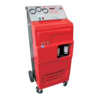
AUTOMATIC UNIT WITH TWO ELECTRONIC REFRIGERANT SCALES
FOR RECOVERY,RECYCLING,EVA- CUATION AND RECHARGE
STATION AUTOMATIQUE AVEC DEUX BALANCES ÉLECTRONIQUES
POUR LA RÉCUPÉRATION, LE RECYCLAGE,LE TIRAGE À VIDE ET LA
CHARGE
AUTOMATMITZWEIELEKTRONISCHENWAAGENZUM
ABSAUGEN,RECYCLENEVAKUIERENUNDBEFÜLLEN
ESTACIÓN AUTOMÁTICA DE RECUPERACIÓN, RECIRCULACIÓN,
VACÍO Y CARGA CON DOS BÁSCULAS ELECTRÓNICAS
FR2001.6
Werther1-35,39-42
Question and Answer IconNeed help?

Do you have a question about the WERTHER INTERNATIONAL FR2001.6 and is the answer not in the manual?

WERTHER INTERNATIONAL FR2001.6 Specifications

General IconGeneral
BrandWERTHER INTERNATIONAL
ModelFR2001.6
CategoryBattery Charger
LanguageEnglish

Summary

Chapter 1 Specifications

Technical Data

Detailed specifications for the unit's components and capabilities.

Chapter 2 Safety Rules

General Safety Warnings

Crucial safety precautions for operating the refrigerant handling unit.

Chapter 3 Preparation of the System

System Preparation Steps

Procedures for scale release, oil refilling, power connection, and display info.

Settings and Configuration

Accessing and configuring unit settings like language, vacuum, and calibration.

Chapter 4 Operation

Cycle Modes Overview

Explanation of manual, automatic, and database-assisted operating modes.

Automatic Cycle Operation

Step-by-step process for the automatic refrigerant recovery cycle.

Manual Cycle Operation

Detailed steps for manual recovery, vacuum, and charge phases.

Alarms and System Pressure Control

Understanding unit alarms and monitoring A/C system pressures.

Wiring Diagram

Wiring Diagram Components

Identification and description of electrical components in the wiring diagram.

Flow Diagram

Flow Diagram Components

Identification and description of components in the refrigerant flow diagram.

Chapter 5 Troubleshooting

Troubleshooting Guide

Systematic approach to identifying and resolving common unit malfunctions.

Chapter 6 Maintenance

Routine Maintenance Procedures

Schedule and procedure for initial checks, pump oil, and filter replacement.

Chapter 7 Spare Parts

Spare Parts Ordering Procedure

Instructions for ordering replacement parts, including required information.