INSTALLATION
1. This light has one surface coated with adhesive. For
best results make sure the surface where the light will
be installed is clean and free of dust or dirt before
mounting the light.
2. Measure for desired placement and assemble your
lighting system before installing.
a. Maximum total length for all strips connected to a
single supply is length of one tape light, either 2M or 4M.
b. This light should not be connected to another strip
when doing so will result in the strip on one supply being
greater than length of one tape light, either 2M or 4M.
c. Never electrically connect two light strips that have
separate supplies. Doing so can Damage the lights and
present a risk of re or injury.
3. Only cut light strip at the point where scissors & appear
on the light surface
a. When assembling product make sure all connections
are secure in order to assure that the product will
operate satisfactorily for its expected useful life
4. After the assembled light has been tested peel backing
paper from the rear of the light and press the adhesive
side of the light to the surface
5. Connect power supply to light and plug into wall outlet
in compliance with local regulations.
CAUTION:
If light is creased or bent in too sharp an angle it will be
permanently Damaged!
If bend in the light is between LEDs the radius of the
bend must be no less than 5/8 inch.
If the bend in the light is near the LED then the radius of
the bend must be greater than 1 inch.
INSTALLATION OF CONNECTOR STRIPS
Materials needed:
Tape light, scissors, connector cable, pliers, connector cover
1. This strip light can be cut to length and lengths can be
reconnected to t custom installation space as required.
2. Measure for desired placement and assemble all
connections to your lighting system before installing.
a. Maximum total length for all strips connected to a
single supply is length of one tape light, either 2M or 4M.
b. This light should not be connected to another strip
when doing so will result in the strip attached to one
supply being greater than length of one tape light, either
2M or 4M.
c. Never electrically connect two light strips that have
separate supplies. Doing so can Damage the lights and
present a risk of re or injury.
3. Measure tape light to desired length. Then nd nearest
“Cut Line” (Line with scissors) that will allow the strip to be
installed in the desired location.
a. Only cut light strip at the point where scissors & appear
on the light surface. 4 pin tape light shown. White tape
only has 2 pins.
b. Locate the 2 or 4 copper colored strips on either
side of the Cut Line. These will be the contacts for the
connector cable. After the tape is cut carefully remove
½ inch of the protective paper from the rear of the light
on each of the cut ends to expose the connection
copper colored strips on the rear of the light.
c. Lay connector cable on at surface with connection
pins facing up.
d. Place cut end of the tape light, with LEDs facing
up, into the connector housing . the cut end of the
connector should rest against the barrier on the cable
side of the connector. The end should not extend
beyond or on top of this barrier.
e. When the cut end is against the barrier the connection
pins will be located under the copper colored strips on
the bottom of the tape light. These copper colored strips
will become the connection points for the cable.
f. Place the connector cover into the two slots provided
in the cable connector on either side of the cut end.
Press the cover down hard so the connection pins pierce
the Tape light cut end.
g. After pressing the cover down hard use the pliers to
carefully press the cover intop the connector and secure
the connection.
h. Repeat this process for the connector and cut end on
the opposite side of the cable.
i. When assembling product make sure all connections
are secure in order to assure that the product will
operate satisfactorily for its expected useful life.
j. Check the assembled Tape light before installation to
verify connections are properly assembled.
4. Install light by removing the tape from the back and
pressing it onto the clean mounting surface
WESTEK LTAPE and LTAPE-RGB Series Tape Lights
Models: LTAPE2M, LTAPE2MRGB, LTAPE4M, LTAPE4MRGB
IMPORTANT SAFETY INSTRUCTIONS
CAUTION: TO REDUCE THE RISK OF FIRE, ELECTRIC SHOCK OR INJURY TO PERSONS.
1. If you have any concerns about the installation of this product consult a licensed electrician before continuing.
2. Unplug before performing maintenance on this system.
3. Use only insulated staples or plastic ties to secure cords.
4. Route or secure cords so they will not be pinched or damaged when the cabinet is pushed to the wall.
5. Not intended for recessed installation in softs or ceilings.
6. The national electrical code (NEC) does not permit cords to be concealed where damage to insulation may go
unnoticed. To prevent re danger, do not run cord behind walls or in ceilings, softs, or cabinets where they may
be inaccessible for examination. Cords should be visually examined periodically and immediately replaced when
damage is noted.
Make sure to read and understand instructions fully before beginning installation of this light. Failure to do so may result
in Fire, Injury, or damage to the product. Keep the instruction manual supplied with this product so it can be consulted
during installation or maintenance of the light.
1. This strip light can be cut to length and lengths can be reconnected to t custom installation space as required.
2. Always pay attention to the technical data provided on each product.
3. Never operate this strip while it is coiled on the packing reel. Excess heat may damage the strip.
4. Never use this strip light in an area where there is danger of explosion. Do not operate near ammable liquids or
gases. Keep away from curtains, draperies or other combustible aterials.
5. There are no replaceable bulbs in this light.
6. For Indoor/Outdoor Use. Not to be exposed to direct sunlight. Safe for use outside as long as receiver box remains
sheltered from moisture.
7. Danger of eye damage. Do not look directly into the LED while it is lit.
8. This is a class III device. The light is supplied by an isolated 12 V supply.
9. This light strip should only be used with the driver provided in the kit.
10. Waste electrical products should be disposed of in a manner that is in compliance with local regulations.
CET
LED TAPE LIGHT
COLOR CHANGING LED TAPE LIGHT
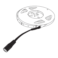
White Tape Light Installation
White LED / DEL blanche / LED blanco
Model: LTAPE2M - 2M (6.6 ft)
White LED / DEL blanche / LED blanco
Model: LTAPE4M - 4M (13 ft)
Color LED / DEL de couleur / LED de color
Model: LTAPE2MRGB - 2M (6.6 ft)
Color LED / DEL de couleur / LED de color
Model: LTAPE4MRGB - 4M (13 ft)