116072-2004
••• •
•• • •
•••
••• •
•••
•••
10 10 10 11 11 119
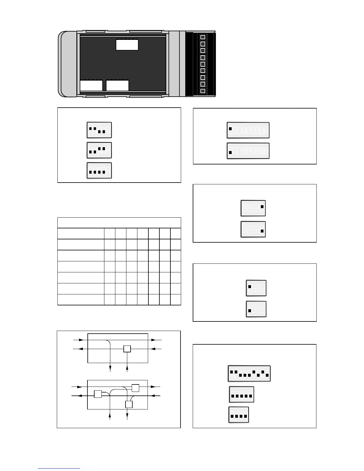
Supervision table when selecting data bits
7 bits
8 bits
No parity
Parity
1 stop bit
2 stop bits
Number of bits
Termination with fail-safe
Termination (2-wire)
S2
Termination (4-wire)
S2
No termination
S2
Transmitted power channel 1
Low
S2
High
S2
Transmitted power channel 2
Low
The fail-safe function forces the signal state of the
receiver to OFF when the connected
transmitter is in tri-state (transmitter inactive).
The receiver located furthest away shall be terminated.
S3
High
S3
ON
1234
ON
1234
ON
12345
ON
12345
Factory settings
S1
ON
123456789
S3
ON
1234
S2
ON
12345
Selection of 2- or 4-wire
4-wire
S1
ON
123456789
2-wire
S1
ON
123456789
Selection of 2-wire RS-485 or 4-wire RS-422.
For RS-232/V.24 S1:1 can be ignored.
ON
12345
12345
ON
12345
ON
F/O
V-function
Y-function
F/O
F/O F/O
RS-232/V.24 / RS-422/485
RS-232/V.24 / RS-422/485
channel 1 channel 2
channel 1 channel 2
Description V/Y-function
Normally high power is used. Low power is used with fibre
lengths shorter than 100 m.
Normally high power is used. Low power is used with fibre
lengths shorter than 100 m. S3: 2–4 is not used.
 Loading...