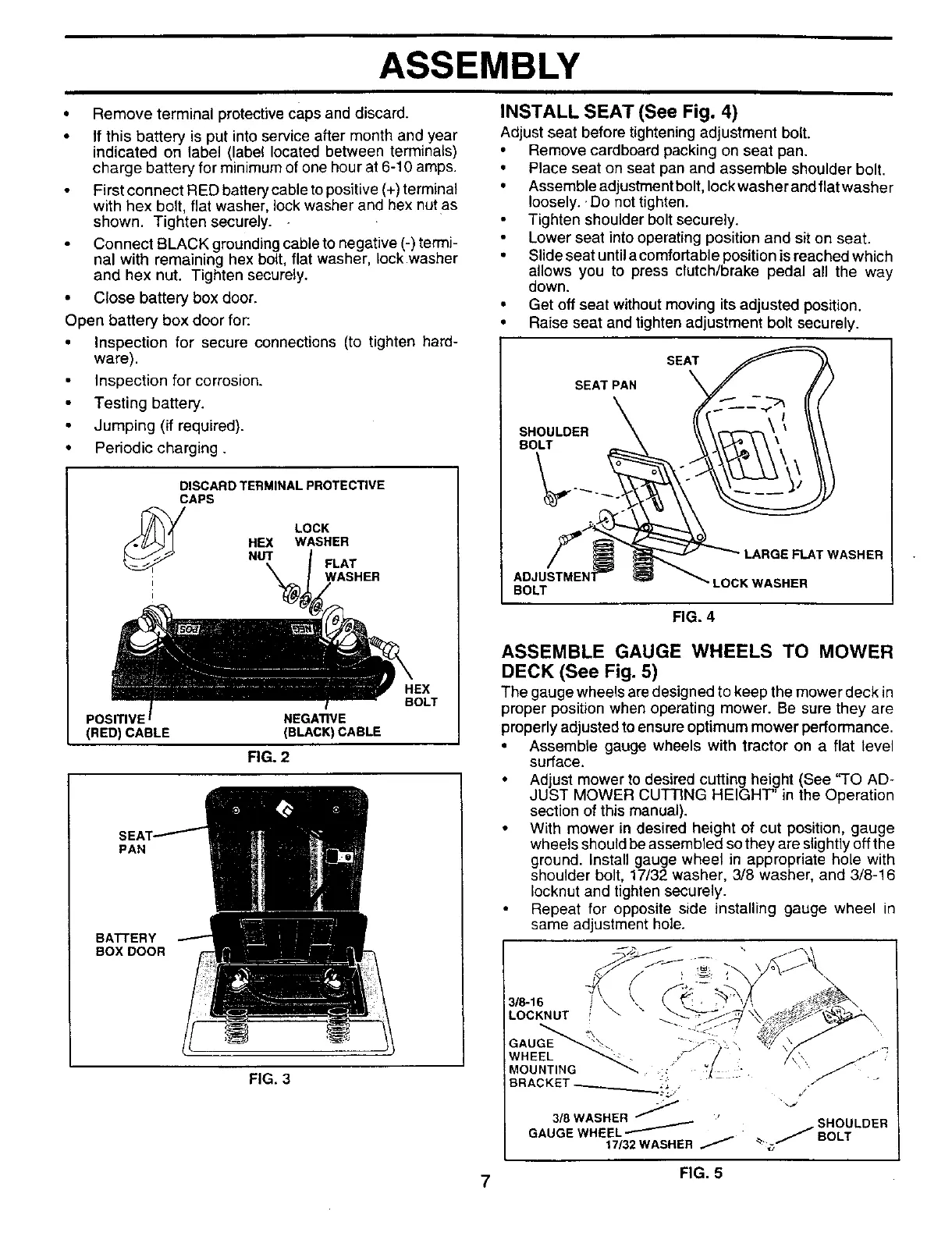
ASSEMBLY
• Remove terminal protective caps and discard.
• If this battery is put into service after month and year
indicated on label (label located between terminals)
charge battery for minimum of one hour at 6-10 amps.
First connect RED battery cable to positive (+) terminal
with hex bolt, flat washer, lock washer and hex nutas
shown. Tighten securely. -
Connect BLACK grounding cable to negative (-) termi-
nal with remaining hex bolt, flat washer, lock washer
and hex nut. Tighten securely.
• Close battery box door.
Open battery box door for:
• Inspection for secure connections (to tighten hard-
ware).
Inspection for corrosion.
Testing battery.
Jumping (if required).
• Periodic charging.
DISCARD TERMINAL PROTECTIVE
CAPS
LOCK
HEX WASHER
NUT FLAT
WASHER
POSITIVE NEGATIVE
(RED) CABLE (BLACK) CABLE
RG. 2
BOLT
PAN
BAI-rERY
BOX DOOR
FIG. 3
INSTALL SEAT (See Fig. 4)
Adjust seat before tighteningadjustment bolt.
• Remove cardboard packing on seat pan.
• Place seat on seat pan and assemble shoulder bolt.
• Assemble adjustment bolt, lock washer and flat washer
loosely.. Do not tighten.
Tighten shoulder bolt securely.
Lower seat into operating position and sit on seat.
• Slide seat until a comfortable position is reached which
allows you to press clutch/brake pedal all the way
down.
• Get off seat without moving its adjusted position.
• Raise seat and tighten adjustment bolt securely.
SEAT
SEAT PAN
SHOULDER
BOLT
LARGE FLAT WASHER
BOLT
"LOCK WASHER
FIG. 4
ASSEMBLE GAUGE WHEELS TO MOWER
DECK (See Fig. 5)
The gauge wheels are designed to keep the mower deck in
proper position when operating mower. Be sure they are
properly adjusted to ensure optimum mower performance.
• Assemble gauge wheels with tractor on a flat level
surface.
• Adjust mower to desired cutting height (See "TO AD-
JUST MOWER CUTTING HEIGHT' in the Operation
section of this manual).
• With mower in desired height of cut position, gauge
wheels should be assembled so they are slightly off the
ground. Install gauge wheel in appropriate hole with
shoulder bolt, 17/32 washer, 3/8 washer, and 3/8-16
lecknut and tighten securely.
Repeat for opposite side installing gauge wheel in
same ad ustment hole.
3/_16
LOCKNUT
\
y •
.OU,T,NO
BRACKET-__________._;.., _,
318 WASHER
SHOULDER
GAUGE WHEEL _
17132WASHER _ _. _BOLT
7 FIG. 5
 Loading...