W2069 WSW PRIME RANGE Built-in Unit O&M 20231025.docx Page 3 Westin
4.4. Electrical Installation
The Prime extractor is a fixed electrical appliance.
The extractor is a stationary appliance supplied with an
electrical supply flex and moulded 3 pin UK plug (3A) for
connection to the electrical supply.
The appliance must be fed from a 230Vac single phase
electrical supply. You may wish to terminate the electrical
supply using a standard mains electrical socket positioned
close to the extractors intended location.
Alternatively, you may terminate the electrical supply from a
switched-fused spur. The spur should be located adjacent to
the hood/cooker so that the supply can be disconnected from
the hood using the switch. The means of disconnection from
the supply must have a minimum contact separation of 3mm
in all poles. A competent Part P registered electrical technician
must perform the electrical installation.
The mains supply is connected as follows:
Make sure the switched-fused spur supplying the extractor is in
the off position before connecting the appliance to the electrical
supply.
4.5. Fixing the Extractor in Position
Please note the following prior to commencing fixing the
extractor in position:
• Two people are required to install units over 900mm wide;
to lift, hold and fix the unit in position.
• The unit will need supporting close to the opening when
attaching the ducting and making electrical connections.
• As described in 4.2 (Ducting Requirements), ducting should
have been installed so that a semi rigid or flexible portion is
hangs down through the soffit opening.
• Do not remove protective tape until after the installation.
Proceed as follows:
• Remove the grease filters as described in Section 7.
• For Rear Outlet Models Only, separate the blower
assemblies from the rear of the appliance and pull them
back into the extractor so that the duct spigots no longer
protrude from the hood rear.
• The extractor is held securely in place within the furniture
opening by 4 adjustable spring toggle clips that protrude
through slots in the outer casing of the unit.
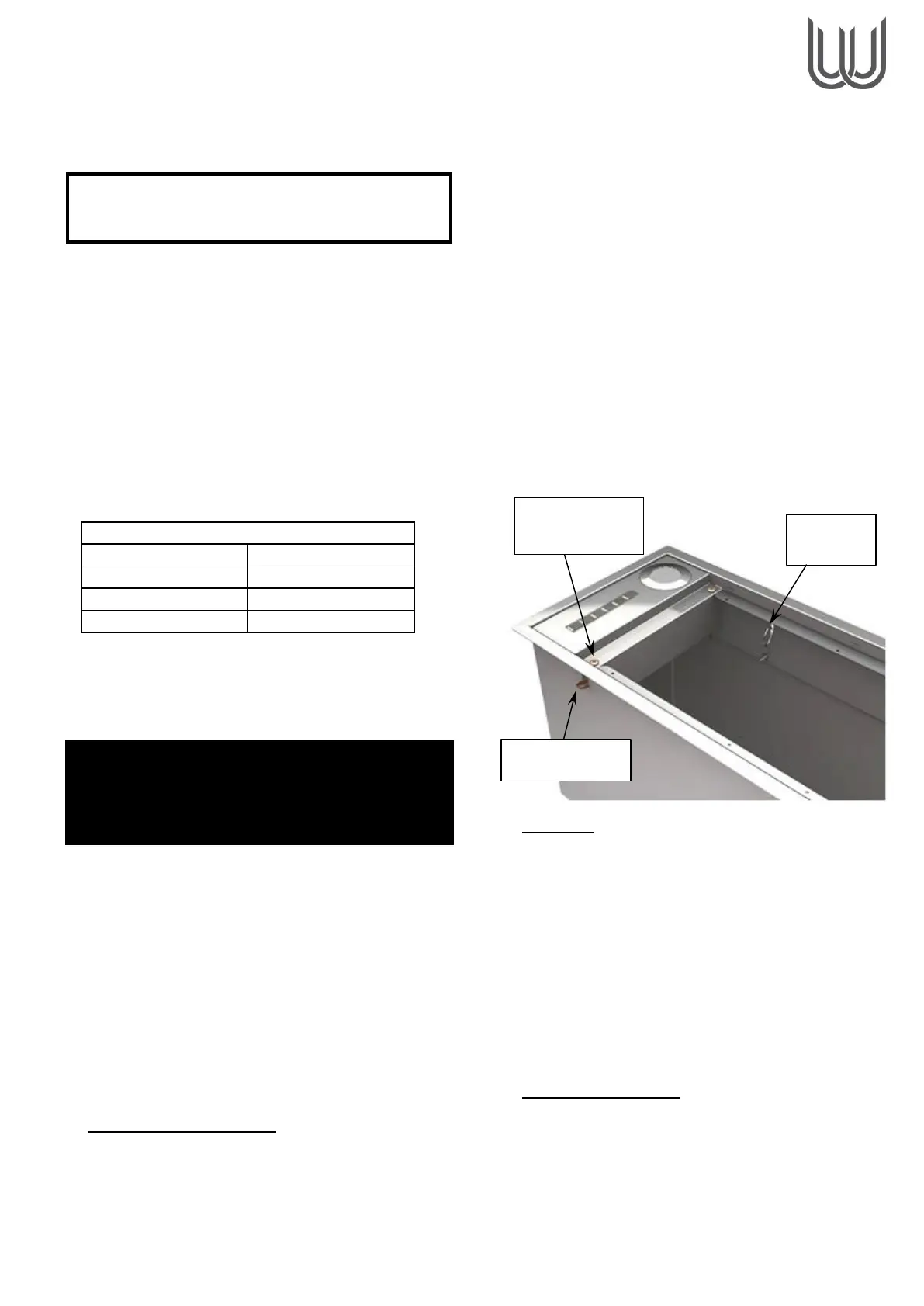
Screws for adjusting the height of the spring toggle clips are
located behind the grease filters, set into the left and right
filter opening flange (See Fig 1).
The spring toggle clips are moved up (away from the base
flange) by turning the screws anti-clockwise and down
(towards the flange) by turning the screws clockwise.
Do not use power drivers to turn the spring toggle clip
height adjustment screws.
Ensure that all spring toggle clips are adjusted such
that each is in the fully open position at the top of its
slot and can fold fully in and out of the slot when
pushed. A fully open clip flap will protrude from the casing
by approximately 10mm.
• Supplementary support of the unit is provided by two sprung
wire safety clips which are there to prevent the extractor
falling during removal. The wire safety clips should be
disabled for installation by pulling the clip release ring
back until the clip is clear of its slot in the body of the
extractor and then sliding it over to one side, so that the wire
clip no longer protrudes through its slot but rests against the
inner casing of the extractor.
––––
• Top Outlet - Position the extractor face down and as
close to the opening as is practical.
Tip: A platform to rest the extractor on and support it close
to the opening is advisable. This will remove the need for
excessive duct lengths hanging down through the opening
to reach the spigot with the extractor at worktop level. The
box the appliance came in can be used as a handy platform.
• Cut off any excess ducting and connect the ducting to the
extractor exhaust spigot using plastic tie straps or a
suitable alternative (e.g. jubilee clip) – we do not
recommend duct tape as the sole means of connection.
Note: Internal motor models have non-return flaps as part of
the spigot assembly to reduce air blowing back into the unit
from outside.
• Rear outlet models only
• Note: Rear Outlet models are not recommended if enough
height above a Top Outlet Cache would exist to
accommodate a bend in the ducting. If a bend can be
accommodated, then the Top Outlet model is always
desirable due to reduced installation complexity.
• If a Rear Outlet Model must be installed, then the duct
cannot be attached prior to installation because the duct
 Loading...