EasyManua.ls Logo

Westinghouse 30-471 (E) User Manual

Westinghouse 30-471 (E)
14 pages
To Next Page IconTo Next Page
Page #1 background imageLoading...
Page #1 background image
Instruction Leaflet
30-471 (E)
Page 1
Westinghouse Canada
Electronics, Control and Distribution Products Division
September, 1984
New Information
Robonic II Automatic
Transfer Switches
Operation and
Maintenance Manual
Index
Warranty ......................................... 2
Westinghouse Offices ..................... 3
General Description ........................ 4
Component Identification ................ 7
LRO Description ............................. 5
RO Description ............................... 6
PRO Description ............................. 6
Application Information ................... 7
Logic Control .................................. 7
Replacing Parts ............................ 13
Trouble Shooting Guide ................ 14
Recommended Maintenance ........ 14
AUTOMATIC TRANSFER SWITCH
Question and Answer IconNeed help?

Do you have a question about the Westinghouse 30-471 (E) and is the answer not in the manual?

Westinghouse 30-471 (E) Specifications

General IconGeneral
TypeToggle Switch
Amperage15 A
Actuator TypeToggle
MaterialThermoplastic
ColorIvory
PolesSingle Pole
TerminationScrew Terminal

Summary

Warranty Information

Shipping Damage Inspection

Crucial shipping damage inspection instructions.

Westinghouse Sales and Service Directory

WESCO Sales Offices

Locations for product application, delivery, or pricing information.

Westinghouse Service Centres

Locations for after-sales service, installation, and repairs.

General Description of Robonic II Switches

CSA Standard Definitions

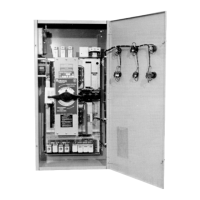
Defines automatic transfer switch types A and B.

Mechanical Component Identification

Type LRO Robonic II Automatic Transfer Switch

LRO Transfer Mechanism Operation

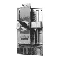
Details the lever-operated mechanism and its positions.

Type "RO" Robonic II Automatic Transfer Switch

Type "PRO" Robonic II Automatic Transfer Switch

Details the gear-driven mechanism and operation of Type PRO switches.

Logic Control Modules

Voltage Sensing Modules

Describes voltage sensing modules for control logic.

Frequency Sensing Modules

Frequency Sensing Module Details

Details frequency sensing modules for control logic.

Additional Control Modules

Relay Driver and Blank Modules

Describes relay driver, undervoltage/underfrequency, and blank modules.

Time Delay Modules

Time Delay Module Types

Lists various time delay modules for TDEC and TDNE functions.

Module Adjustments

Undervoltage & Overvoltage Module Adjustment

Step-by-step guide for adjusting voltage sensing modules.

Time Delay Relay Adjustment

Details adjustments for DT and DTM time delay relays.

Transformer Modules and Plant Exerciser

Plant Exerciser Operation

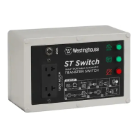
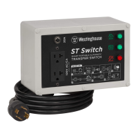
Describes the Plant Exerciser's function and application for automation.

Plant Exerciser Instructions and Testing

Portable Test Kit #50

Describes a test kit for field testing and calibration of modules.

Robonic II Transfer Switch Schematic

Control Circuit Operation Explained

Explains the sequence of operations during power failures and restoration.

Replacing Parts and Components

Parts Common to Robonic II

Lists common plug-in modules and options.

Model-Specific Replacement Parts

Lists parts for LRO, RO, and PRO models.

Troubleshooting and Maintenance

Recommended Maintenance Practices

Guidelines for maintaining Robonic II transfer switches.

Related product manuals