6.2 Electrical Ratings
6.
2.1
Maximum System Voltage
600 V. @
50/60
Hz.
6.2.2
WITHSTAND
Primary Amps Time Seconds
200KA
50KA
@
4KA
~Except
1
KA
on 12A. Solid
6.2.3 DIELECTRIC WITHSTAND
0.05
0.3
Continuous
Windings to Mounting Holes - 3
KV
Windings to Inner Core Surface - 3KV
Mounting Surface to Inner Core Surface - 3KV
6.
2.
4 MAXIMUM
ERROR
SIGNAL - WITH
BOLTED PHASE THROUGH
FAULT
12A Solid
60A Solid
1200A Solid
60/
1200 A
R/L
1.0
A@
144A
5.0
A@720A
100
A@
14.4
KA
100
A@
15
KA
Neutral
Disconnect
Link
NEC
230-
75
Main
___
,.,._,__*
__
..._
___
~
c.
I
Grounding
Electrode
Conductor
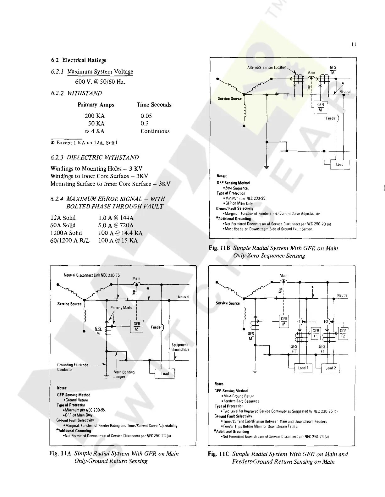
Notes:
GFP
Sensing
Method
•Ground
Return
Type
of
Protection
GFS
"M
•Minimum
per
NEC
230-95
•
GFP
on
Mam
Only
Ground
Fault
Selectivity
~I
I
Polarity
Marks
Mam
Bonding
Jumper
Feeder)
Neutral
Equipment
Sround
Bus
•Marginal.
Function
of
Feeder
Rating
and
Time/Current
Curve
Ad1ustabil1ty.
*Additional
Grounding
•Not
Permitted
Downstream
of
Service
Dtsconnect
per
NEC
250-23
ia).
Fig. 1
lA
Simple Radial System With GFR on Main
Only-Ground Return Sensing
Alternate
Sensor
Location
GfS
feeder)
Notes:
G
FP
Sensing
Method
•Zero
Sequence
Type
of
Protection
•
Mm1mum
per
NEC
230-95
•
Gf
Pon
Mam
Only
Ground
Fault
Selectivity
•Marginal.
function
of
feeder
Time/Current
Curve
Ad1ustab1l1ty
*Additional
Grounding
•Not
Permitted
Downstream
of
Service
01sconnec1
per
NEC
250-23
Jal
•Must
Not
be
on
Downstream
Side
ol
Ground
Fault
Sensor
Load
Fig. l
lB
Simple Radial System With GFR on
Main
Only-Zero Sequence Sensing
Service
Source
Notes:
GfS
M
GFP
Sensing
Method
•Main-Ground
Return
•Feeders-Zero
Sequence
Type
of
Protection
~'-----------
*
Neutral
•Two
Level
tor
Improved
Service
Cont1nu1ty
as
Suggested
by
NEC
230
95
lbl
Ground
Fault
Selectivity
•Time/Current
Coordination
Between
Main
and
Downstream
Feeders
•feeder
Trtps
Before
Mam
tor
Downstream
faults
*Additional
Grounding
•Not
Permitted
Downstream
of
Service
Disconnect
per
NEC
250-23
Ja)
Fig.
llC
Simple Radial System With GFR on Main and
Feeders-Ground Return Sensing on
Main
11
Courtesy of NationalSwitchgear.com
 Loading...