WHL-012 REV. 12.17.14
Gas Fired
Residential
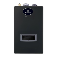
Combi Boiler
Wall Mount Models
INSTALLATION / START-UP
MAINTENANCE / PARTS
WARRANTY
Models
WBRCNG140W
WBRCLP140W
Heat Exchanger Bears the ASME “H” Stamp
NOTICE: Westinghouse reserves the right to make product changes or updates without notice and will not be held liable for
typographical errors in literature.
NOTE TO CONSUMER: PLEASE KEEP ALL INSTRUCTIONS FOR FUTURE REFERENCE.
The surfaces of these products contacted by consumable water contain less than 0.25% lead by weight, as required by the Safe
Drinking Water Act, Section 1417.
IF THE INFORMATION IN THIS MANUAL IS NOT FOLLOWED EXACTLY, A FIRE OR EXPLOSION MAY RESULT, CAUSING
PROPERTY DAMAGE, PERSONAL INJURY, OR LOSS OF LIFE. DO NOT STORE GASOLINE OR OTHER FLAMMABLE VAPORS
AND LIQUIDS IN THE VICINITY OF THIS OR ANY OTHER APPLIANCE.
WHAT TO DO IF YOU SMELL GAS
Do not try to light any appliance.
Do not touch any electrical switch.
Do not use any phone in your building.
Immediately call your gas supplier from a neighbor’s phone. Follow the gas supplier’s instructions.
If you cannot reach your gas supplier, call the fire department. Installation and service must be provided by a qualified installer,
service agency, or the gas supplier.