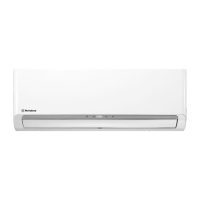
This document serves as a service manual for Westinghouse wall-mounted inverter heat pump air conditioners, specifically models WHZ09WMA21S and WHZ12WMA21S (indoor units) and WHZ09SZA21S and WHZ12SZA21S (outdoor units). It provides essential information for safe installation, operation, maintenance, and troubleshooting.
Function Description
The device is a wall-mounted air conditioning system designed for both cooling and heating, utilizing R410A refrigerant and inverter technology for energy efficiency. It consists of an indoor unit and an outdoor unit that work in conjunction to regulate indoor temperature and humidity.
Important Technical Specifications
The manual details specifications for two main indoor unit models (WHZ09WMA21S and WHZ12WMA21S) and corresponding outdoor unit models (WHZ09SZA21S and WHZ12SZA21S).
Indoor Unit Specifications (WHZ09WMA21S / WHZ12WMA21S):
- Power Supply: 208/230 V ~ 60 Hz, available voltage range 187-253 V.
- Cooling Capacity:
- WHZ09WMA21S: Rated 2.64 kW (9,000 Btu/h), Min.-Max. 1.06-2.93 kW (3,600-10,000 Btu/h).
- WHZ12WMA21S: Rated 3.52 kW (12,000 Btu/h), Min.-Max. 1.17-3.96 kW (4,000-13,500 Btu/h).
- Heating Capacity:
- WHZ09WMA21S: Rated 3.08 kW (10,500 Btu/h), Min.-Max. 1.06-3.08 kW (3,600-10,500 Btu/h).
- WHZ12WMA21S: Rated 3.81 kW (13,000 Btu/h), Min.-Max. 1.17-4.10 kW (4,000-14,000 Btu/h).
- Input Power (Cooling/Heating):
- WHZ09WMA21S: Cooling Rated 0.560 kW, Heating Rated 0.770 kW.
- WHZ12WMA21S: Cooling Rated 0.780 kW, Heating Rated 0.855 kW.
- EER (Cooling): WHZ09WMA21S: 4.71 (16.07 Btu/hW), WHZ12WMA21S: 4.51 (15.40 Btu/hW).
- COP (Heating): WHZ09WMA21S: 4.00 (13.64 Btu/hW), WHZ12WMA21S: 4.45 (15.20 Btu/hW).
- SEER (Cooling): WHZ09WMA21S: 28.0, WHZ12WMA21S: 25.0.
- HSPF (Heating): WHZ09WMA21S: 12.5, WHZ12WMA21S: 12.0.
- Moisture Removal: WHZ09WMA21S: 1.9 pints/h (0.9 L/h), WHZ12WMA21S: 2.5 pints/h (1.2 L/h).
- Airflow Rate (CFM/m³/h): Multiple settings from LOWER to HIGHER, e.g., WHZ09WMA21S Cooling HIGHER 394 (670), WHZ12WMA21S Cooling HIGHER 618 (1,050).
- Sound Pressure Level (dB(A)): Multiple settings from LOWER to HIGHER, e.g., WHZ09WMA21S Cooling HIGHER 42, WHZ12WMA21S Cooling HIGHER 48.
- Dimensions (H x W x D):
- WHZ09WMA21S: 11-9/16 × 24-7/16 × 1-1/16 in (294 x 620 x 27.2 mm).
- WHZ12WMA21S: 14-7/8 x 27-3/4 × 1-1/16 in (378 x 705 x 27.2 mm).
- Weight (Net): WHZ09WMA21S: 20 lb (9 kg), WHZ12WMA21S: 29 lb (13 kg).
- Refrigerant Pipe Connections: Liquid Ø1/4 (Ø6.35) in, Gas Ø3/8 (Ø9.52) in.
- Operation Range: Cooling 61 to 86 °F (16 to 30 °C), Heating 61 to 86 °F (16 to 30 °C).
Outdoor Unit Specifications (WHZ09SZA21S / WHZ12SZA21S):
- Power Supply: 208/230 V ~ 60 Hz, available voltage range 187-253 V.
- Airflow Rate: 1,177 CFM (2,000 m³/h).
- Sound Pressure Level: WHZ09SZA21S: 55 dB(A), WHZ12SZA21S: 55 dB(A).
- Dimensions (H x W x D):
- WHZ09SZA21S: 33-1/16 x 21-1/2 × 11/16 in (840 × 546 × 18.19 mm).
- WHZ12SZA21S: 33-1/16 x 21-1/2 × 11/16 in (840 × 546 × 18.19 mm).
- Weight (Net): WHZ09SZA21S: 75 lb (34 kg), WHZ12SZA21S: 84 lb (38 kg).
- Refrigerant: R410A.
- Refrigerant Oil: VG74 (POE).
- Max. Pipe Length: 65 ft (20 m).
- Max. Height Difference: Indoor unit higher than outdoor unit: 32 ft (10 m), Outdoor unit higher than indoor unit: 16 ft (5 m).
- Operation Range: -0.4 to 115 °F (-18 to 46 °C) for cooling, -13 to 75 °F (-25 to 24 °C) for heating.
Usage Features
The manual emphasizes safe installation and operation, highlighting the importance of following instructions, observing electrical codes, and paying attention to warning and caution notices.
- Installation Space Requirement: Detailed diagrams illustrate minimum clearance distances from the ceiling, walls, and floor for both indoor and outdoor units to ensure proper airflow and safety. For indoor units, this includes over 200 mm/7.9 in from the ceiling, over 50 mm/2 in from the wall, and over 2.4 m/8 ft from the floor. For outdoor units, clearances are over 500 mm/20 in from obstacles and over 250 mm/10 in from walls for air intake and outlet.
- Refrigerant Piping: Instructions for connecting refrigerant tubing using the flare method, applying lubricant, tightening with a torque wrench, and checking for leaks are provided.
- Remote Control: The system is operated via a wireless remote controller (wired option available).
- Operation Test: After installation, a test run is performed by switching on power and using the remote controller to select COOL, HEAT (if applicable), and FAN modes to verify normal operation.
Maintenance Features
The manual outlines procedures for air purging, leakage testing, and comprehensive troubleshooting.
- Air Purging and Leakage Test: A step-by-step guide is provided for connecting a manifold valve and vacuum pump, evacuating the system, checking for vacuum integrity, and performing a leak test to ensure a sealed refrigerant circuit.
- Check After Installation: A checklist of items to verify post-installation, such as firm fixing, refrigerant leakage test, heat insulation, water drainage, correct voltage, secure electrical wiring, proper grounding, specified power cord, unblocked inlet/outlet openings, and recorded pipe length/refrigerant capacity. Possible malfunctions resulting from unaddressed issues are also listed.
- Troubleshooting (Error Code Table):
- Outdoor Unit Indication: Describes how the LED lights on the outdoor control board flash to indicate specific errors. Each error code (e.g., Compressor exhaust temperature too high protection, IPM module protection, Outdoor ambient temperature sensor in trouble) is associated with possible root causes (e.g., sensor failure, refrigerant issues, board failure, wiring problems).
- Compressor Operating Frequency Limitations: Explains how LED indicators (LED1, LED2, LED3) signal reasons for compressor frequency limitations, such as normal operation, over-current, anti-freezing, high discharge temperature, low power voltage, fixed frequency operation, outdoor overload, communication fault, or power-saving.
- Indoor Unit Indication: Details how a 7-segment tube on the indoor display board shows error codes (e.g., "EA" for communication failure between display board and control board) and their root causes. It also describes a method to retrieve error codes by pressing the "Sleep" button on the remote controller 10 times in 10 seconds.
- Trouble Diagnosis of Specific Components:
- Compressor: Guidance on identifying inverter compressor terminals (connect in the same way as original unit) and measuring coil resistance (a few Ohms, three phases having the same resistance).
- Electric Filter Board: Visual inspection for loose connections and voltage test to ensure input and output voltages are identical.
- Electric Communication: Steps to check wiring, ensure tight connections, and measure voltage fluctuations between S1 and N terminals (should be 0V-24V). If no fluctuations, indoor and outdoor control boards may need replacement.
- Jumper Terminals Test: A method to short out specific blue terminals (CN804) on the outdoor control panel to test if the outdoor unit can run independently, helping to diagnose internal/external communication faults.
- Protection Diagnosis: Explains various protection mechanisms (under-voltage, over-voltage, overcurrent) including conditions for activation, protection actions (e.g., system stops, fans stop), and conditions for release.
- Voltage Protection: Triggers if AC input voltage is outside a protective range for five seconds.
- Current Protection: Triggers if current exceeds a "refrigeration current protection" value for six seconds, leading to compressor and outdoor fan stoppage.
- Frequency Decreasing for Over-current: Compressor frequency decreases if current exceeds a specific value.
- Prohibition of Frequency Increasing: Prevents compressor frequency from rising under certain conditions, such as high discharge temperature or anti-overload of the outdoor coiled pipe.

 Need help?
 General




 To Next Page
