P7
7
Models 1JYT9A, 1JYU1A, 1JYU2A and 1JYU3A
Westward Operating Instructions and Parts Manual
Operation (Continued)
NOTE: Problems in a vehicle's fuel,
ignition, or other systems may prevent
the vehicle from starting. The problem
area will need to be serviced before the
vehicle can be started.
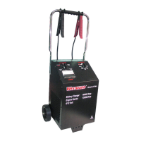
AMMETER
The ammeter on the front of the
charger (see Figure 8) indicates the
amount of amperes owing from the
charger into the battery. As the battery
nears full charge, the charge rate
lessens and the ammeter needle moves
towards lower ampere values. Model
1JYU2A also has green and red lights
installed within the ammeter. The green
light is lit when the battery is at full
charge. The red light indicates that the
battery cables are connected backwards
(takes six seconds before the light will
come on).
When the battery being charged is cold
(temperatures less than 32ºF (0ºC) the
battery will not accept high rates of
charge until it warms up. The initial
charge rate will be low and, as the
battery warms up through charging, the
rate will increase.
The same conditions exist if the battery
being charged is sulfated. Sulfated
batteries cannot accept high charge
rates because the internal plates of the
battery are coated with lead sulfate.
This occurs when a battery is left in a
discharged state for a long time. This
battery condition can sometimes be
cured. The battery can have at least
some of the sulfate removed by
charging on the 2 amp setting (12 volt
only) for a long period of time. Refer to
the battery manufacturer's instructions
for the proper methods of removing
sulfate.
When the battery being charged has a
short circuit, the ammeter will show
that the charger is putting out full
current. If, after 5-10 minutes, the
needle has not moved, unplug the
charger and discontinue charging.
NOTE: If the needle drops to zero, the
internal circuit breaker has tripped and
will reset automatically after 3-4
minutes. Use a voltmeter and read the
voltage of the battery. If the voltage is
under 11.5 volts, the battery is probably
defective and should be serviced or
replaced. If the voltage reads over 11.5
volts, plug the charger back in and
continue charging. If, after 15-20
minutes, the needle on the meter still
has not moved, repeat the voltmeter
test. If no change in voltage has
occurred, the battery needs service or
replacing.
During Engine Start, the needle will
move into the red Engine Start section
of the meter. This will occur when the
vehicle starter is engaged.
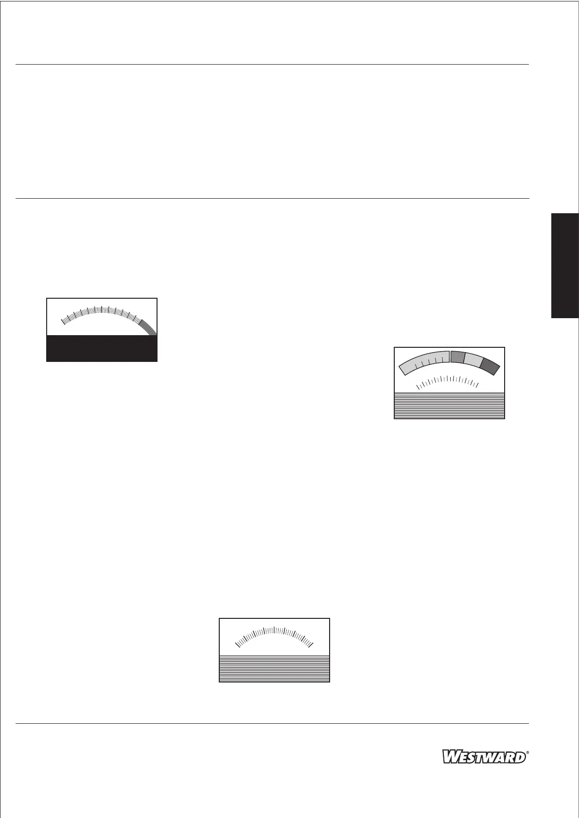
VOLTMETER (1JYU3A ONLY)
The voltmeter (Figure 9) will indicate
voltage whenever the charger is turned
on, or when the clamps are connected
to a battery. If connected to a battery
and on, it will read the combined
voltage of the battery and the charger.
If you get no reading when connected
to a battery, check your connections
and/or your battery.
TEST METER/VOLTMETER
(1JYU1A AND 1JYU2A ONLY)
The combination test meter/voltmeter
on the front of the charger (see Figure
10) is used to read the voltage across
the battery charger clamps.
In normal operation, without the Test
Switch depressed, the meter reads from
0-20 DC volts, on the lower scale of the
meter. Using this part of the meter,
during charging, the voltages should
read:
6 Volt Batteries 6.5 to 8.5 Volts
12 Volt Batteries 13.5 to 16.5 Volts
24 Volt Batteries 27.0 to 33.0 Volts
(1JYU3A Only)
If the voltmeter reads outside of these
voltages, refer to the listings below for
possible battery conditions:
30
20
10
0
40
50
60
AMPS
Figure 8
20
VOLTS
10
30
40
0
Figure 9
DC VOLTS
100
LOW
OK
HIGH
75
50
25
0
%
o
f
C
H
A
R
G
E
A
L
E
R
N
A
T
O
R
T
E
S
T
10
12
14
16
18
20
8
6
4
2
0
Figure 10
E
N
G
L
I
S
H
 Loading...