Example Setting Proles:
1. Tournament legal semi-automatic (NPPL)
a. Fire mode 1 or 2 (semi-auto unlimited or capped)
b. Debounce 5-20
c. AMB 2
d. CPF 2-5
e. Watch time 200ms for Vlocity or 400ms for gravity feed
2. PSP X-Ball, CFOA
a. Fire mode 3, 4, 5, or 6
b. Max rate of re set to 15BPS, depending on Pact Timer readings
c. Debounce 5-20
d. Ramp start 5 or higher if using PSP 50% or 100% ramping
e. Watch time 200ms for Vlocity or 400ms for gravity feed
3. Millennium
a. Fire mode 4, 5, 9, or 10 (PSP or normal ramping modes)
b. Max rate of re set to 15 BPS, depending on Pact Timer readings
c. Debounce 5-20
d. Ramp start 8 or higher
e. Watch time 200ms for Vlocity or 400ms for gravity feed
4. NXL
a. Fire mode 7 (NXL full-automatic).
b. Max rate of re set to 15 BPS, depending on Pact Timer readings
c. Debounce 5-20
d. Watch time 200ms for Vlocity or 400ms for gravity feed
5. Speed (absolute fastest/bounciest)
a. Any re mode
b. Max rate of re set to unlimited
c. Debounce 1
d. AMB 1 if using semi-automatic
e. CPF 1
f. Ramp start 4 if using any ramping modes
Additional Features
A tip for setting the debounce, AMB, and CPF – This only applies to semi-automatic re modes (modes 1 and 2) since AMB is disabled in the PSP re modes or NXL mode.
Debounce, AMB, CPF setup steps, while using paint and air:
1. Turn AMB and CPF off (set both to 1).
2. Starting at debounce 1-3, raise the debounce setting a notch at a time until excessive trigger bounce goes away. The goal is to have one pull, one shot, regardless of rate of re. Do NOT slow
pull test for bounce during this phase. Instead, pull the trigger rapidly or walk it, listening for double or triple res.
3. When it appears that it is only one shot, one pull for solid trigger pulls, try the slow pull test. Holding the marker steady, slowly pull the trigger and see if multiple shots can be generated from
the single pull.
4. Increase the CPF setting a notch at a time until the slow pull bounce starts to disappear. An additional test is to re a few rounds quickly, then hold the trigger right on the activation point to see
if the marker will run away.
5. If you reach setting 10 with CPF and the marker can still be slow pulled to re full-automatic, your debounce setting is probably too low. Go back to step 2.
6. AMB should not be set above 3, if possible, since it is not as transparent to the user as CPF. Even a CPF setting of 10 will not be noticed by the user.
In order to maximize rate of re you need to run the sear ON, loader delay, open delay, and close time as low as possible, without affecting velocity or blowback. This is only intended to see
how fast you can set up the marker to shoot. We recommend setting the marker to be matched and balanced with your loader. Set up should be made so that your marker will be smooth and
consistent. For example at 15 BPS, your marker should re with a very good stream using a Vlocity loader.
OPERATION AND MAINTENANCE
Operation
Velocity adjustment: Most paintball elds have a limit to ball velocity and will provide a chronograph for the user to check. There are many conditions that will affect velocity. There are 2 ways to
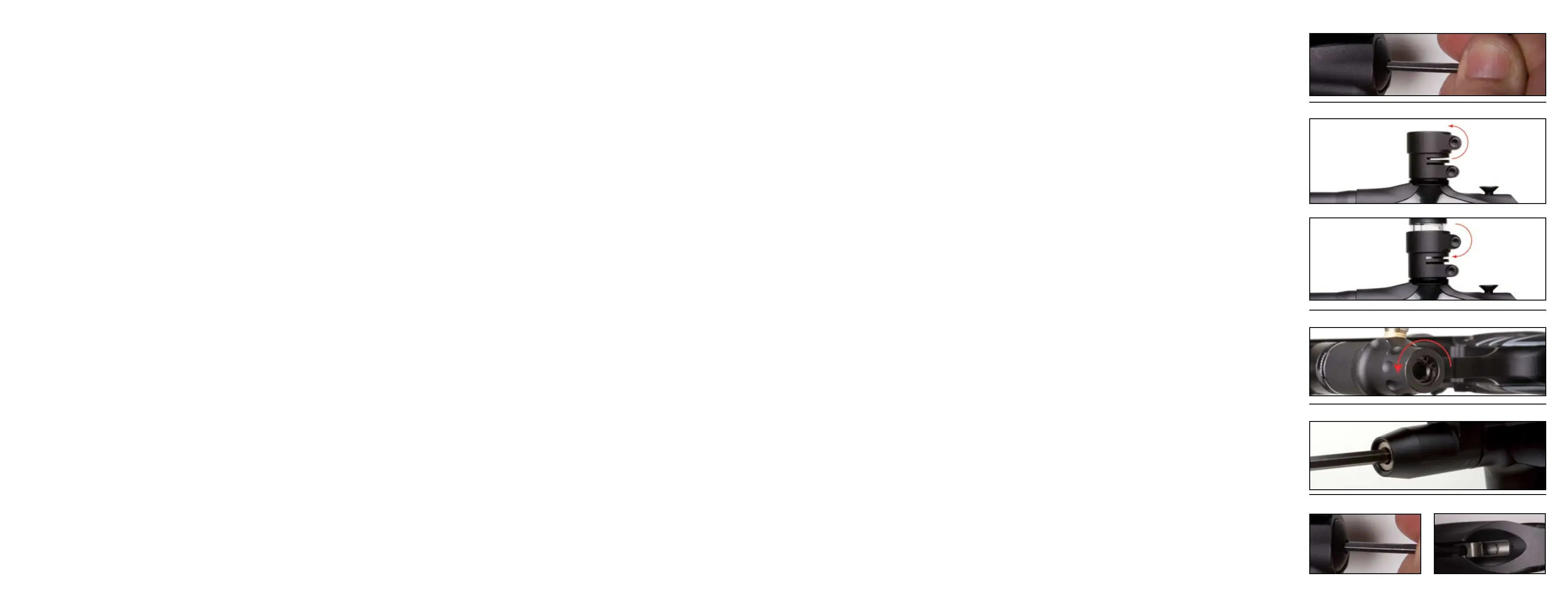
adjust the velocity of the ASR and other traditional Autococker style markers. One is adjustment of the rear IVG. Use a 3/16” Allen key to turn the IVG in to increase the velocity and out to decrease
(Figure 5). The other way velocity can be adjusted is by adjusting the HP regulator (Figure 7). Going up or down in pressure can either increase or decrease your velocity. Make small adjustments
and check your velocity with a couple of shots.
Paintball to barrel t is important with Autockers. Since the ASR is a closed bolt system, once the ball is fully breeched, the bolt will close pushing the ball forward waiting to be red. If the ball is
too small and does not t the barrel correctly, there is a potential for the ball to roll part way down the barrel when the marker is pointed down. The rst shot may be at a low velocity, while the
next one is normal. Point the gun down, and shake the marker. If the ball rolls out of the barrel, the paint is too small for that barrel. If the paint is too big for the barrel, you can get blow back,
and barrel breaks. To check for t, take the barrel off, and put a ball in the end. If you can blow the ball out of the barrel with a light puff of air, it’s ne. If it rolls then it’s too small. If it gets
stuck then the paint is too big. The ASR stock barrel size is .689”. WGP offers barrel kit for adjustment with varying paint sizes. The ASR 2 piece barrel is interchangeable with other WGP Kaner kits.
Newer hopper technology now force paintballs down into the breech and actually apply pressure on the ball. The ASR been designed with new dual ball detents nubs which should eliminate double
feeding. When attaching a hopper, use a 5/32” Allen key to loosen the top rotating clamp (Figure 6). Press the hopper all the way down and tighten screw (Figure 6.2). There are 2 rotating points
on the new rotating feedneck. Some users prefer having the clamp at the front depending on their hopper. Set the feedneck up how you prefer it and tighten both screws before a game. Note:
WGP recommends the use of a higher end hopper, example the View Loader Vlocity.
ASR High Pressure (HP) regulator has been designed for high ow and regulated pressure consistency. It has been set up from the factory with the most consistent setting for the highest perfor-
mance for most users. The regulator is designed to eliminate creep and spiking. There are many variables, depending on weather, temperature, paint, hopper, and playing conditions, the user
may need to make an adjustment to the regulator pressure. Sweet spotting the regulator will give the individual user optimal performance. The regulator maintains a constant pressure thus ring
the ball more consistently and accurately. Velocity could still uctuate due to variations in paintballs but should still be very consistent.
To turn the pressure up, use a 1/4” Allen key and turn the Regulator Adjustment Screw out counterclockwise. To decrease pressure, turn the Regulator Adjustment Screw in clockwise (Figure 7).
To set the regulator for the most consistent, and efcient pressure, rst set the IVG adjuster on you gun to the mid point. It doesn’t have to be exact just close. This is to ensure that if you go out to
a eld and shooting high that you have some room to back it out. Now, turn the regulator down to the point where the gun res consistently and re-cocks. You will probably be shooting under 200
fps. Now slowly turn the regulator up, and chrono after every adjustment. The FPS will go up as the pressure from the regulator goes up. When the velocity stops going up, that’s where you will
get the most shots per tank. If you go up too far past this point, you will actually see the velocity begin to drop. The higher pressure can also be harder on your paint causing more breaks. It’s not
the quietest pressure, but it’s the most efcient.
Now that it’s set up at the most efcient spot you now have to nd the “sweet spot” for the marker. It is typically on most markers just below the setting that’s the most efcient. All you have to
do is play with the pressure a little. Lower the pressure a little and then take a couple of shots over the chronograph. Bring it up a touch, and do it again. It will take a couple of iterations and will
require patience. Note: Use good high quality paint. Try to use paint that you plan on using at the eld to be consistent.
Note: Large adjustments to the HP regulator could affect the Low Pressure Regulator (LPR). User should also check LPR settings, see next section.
The Low Pressure Regulator is located on the front of the new manifold. The regulator controls the amount of pressure applied to the pneumatic valve and ram. If there is not enough pressure to
the ram, the marker may re-cock but not fully and completely. If too high, you could blow out o-rings and gaskets. To adjust the regulator pressure, use a 3/16” Allen key. Start by turning the
adjustment screw out counterclockwise (Figure 8). With the marker ON and pressurized, turn the eyes OFF and re the marker. The bolt should start to move back and re-cock the system. Turn the
screw in clockwise to increase the pressure and apply more force to re-cock. Fire the marker to conrm bolt moves all the way back and re-cock the system. The right pressure re-cocks the system
and has the right feel. If the pressure is too high, the system will re-cock but do it more violently. Safety Note: Always practice safe paintball marker handling and procedures. Conrm Barrel sock
is attached and secured correctly.
Lug adjustment: The lug is what holds the hammer back. Once the solenoid is energized, the sear will trip the hammer sending it forward and ring the marker. The lug position determines how
effectively the hammer is tripped and is very important with Autocockers. If the lug is too low, more time may be required on your SEAR ON time to release the hammer and may not even trip. If
the lug is too high, the hammer may not catch the sear and be held back. Lug adjustment is also considered part of mechanical timing and will affect performance. Mechanical adjustments with
SEAR ON time adjustments will yield the best marker performance. Lug locking and adjustment on the ASR is simple and will require a 1/8” Allen key. Note: Make sure mark is degassed properly
before making any modications to the lug.
First start by loosening the rear lug locking set screw (Figure 9). Remove the bolt. Now turn the lug up or down by inserting you 1/8” Allen key from the top of the marker into the lug
(Figure 9.2). To check position, insert your bolt and cock the marker back manually. Turn the marker ON, and re the marker. If the sear does not release the hammer, turn the lug out. If cocking
the hammer back and the lug does not catch the sear, turn the lug in slowly and re-cock to check if it catches. Once in the correct position, lock the lug in. This process will require patience since
many iterations maybe required. Safety Note: Always practice safe paintball marker handling and procedures. Conrm Barrel sock is attached and secured correctly.
Figure 5
Figure 6
Figure 7
Figure 6.2
Figure 8
Figure 9 Figure 9.2
 Loading...