In-Line Pressure Switch
WU7207(B) / WU7210(B)
INSTALLATION & USER INSTRUCTIONS
Thank you for purchasing this Whale® product. For over 70 years Whale has led the way in the design and manufacture of water and waste systems including:-
plumbing, faucets, showers, pumps and heating for low voltage applications. The company and its products have built a reputation for quality, reliability and innovation
backed up by excellent customer service. For information on our full product range visit: www.whalepumps.com
Typical Installation
The Whale In-Line Pressure Switch is designed for use in freshwater pressure systems without micro-switches. It is suitable for use with 12V d.c. or 24V d.c. Whale
Submersible or Whale In-Line Pumps.This product is designed for use with freshwater only. If it is intended for use with any other liquid, it is the user’s responsibility to
ensure that the materials are fully compatible with the liquids to be used and that a system of safe working practice is applied to installation, use and maintenance.
CONTENTS
1. Principles of Operation
2. Application
3. Warnings
4. Instructions for Installation
5. Operating Instructions
6. Maintenance
7. Service Support Details
8. EU Declaration of Conformity
9. Warranty
The Whale In-Line Pressure Switch is designed to operate in freshwater pressurised systems connected to a 12V d.c.or 24V d.c. power supply in recreational vehicles or
vessels. The pressure switch detects the opening or closing of any tap in the system and switches the pump on or off as required.
The Whale In-Line Pressure Switch is designed for use in freshwater pressurised systems, supplied by either a Whale Submersible or Whale In-Line Pump.
Use for any other purpose or with any other liquid is not recommended and is entirely at the user’s risk.
Observe all warnings.
To the Fitter: Check that the product is suitable for the intended application, follow these installation instructions and ensure all relevant personnel read the points listed
below. Also ensure that these operating instructions are passed on to the end user.
To the User: Please read the following carefully before installation and use.
Before you begin, always disconnect power sources before installing or making connections with all applications. It is important that a system of safe working practice is
applied to the installation, use and maintenance. Always ensure the water system is drained before commencing work.
Step 1 Choose a location to install the In-Line Pressure Switch. When choosing an installation location, you must consider the following:-
i) The location must allow access to the pressure switch for adjustment and mainentance when required.
ii) The pressure switch must be installed in the pipework, on the outlet side of the pump before any T pieces. This means that the opening of any tap in the
system will activate the pressure switch.
iii) The pressure switch must be screwed to a surface or suspended in the pipework.
Step 2 Use Whale 12mm Quick Connect plumbing fi ttings (Whale Part Number: WU1202) to connect the pressure switch to the pipework.
Step 3 Connect microswitch terminals (Fig 2).
Figure 2: Connecting Microswitch Terminals Figure 3: Installing Isolator Switch
Step 4 You must fi t an isolator switch and a fuse (not provided) in the postive line (Fig. 3).
Priming the System
Option 1: In-Line Pressure Switch Fitted With In-Line Pump
Option 2: In-Line Pressure Switch Fitted With Internal Submersible Pump
Option 3: In-Line Pressure Switch Fitted With External Submersible Pump
1
LIST OF IMAGES
1. Pressure Switch Location
2. Connecting Microswitch Terminals
3. Installing Isolator Switch
1. PRINCIPLES OF OPERATION
2. APPLICATION
3. WARNINGS
4. INSTRUCTIONS FOR INSTALLATION
EN
From
Pump
Click x 2
Click x 2
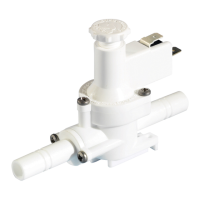
Direction of Water Flow
To Battery +ve via Isolation Switch and Fuse
To Pump +ve
To Outlets
Figure 1: Pressure Switch Location
Between Battery +ve and Pressure Switch
and
Switch
SPST
Fuse
12V dc 5 Amp
24V dc 5 Amp
Direction of Water Flow
To Pump +ve
To Battery +ve (via Isolator
Switch and Fuse)
Pressure adjusting screw
5. INSTRUCTIONS FOR OPERATION