This document provides a parts list, instructions, and service bulletins for the Wheel Horse Rotary Mower, Model 5-1421.
Function Description:
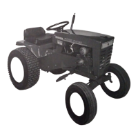
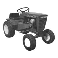
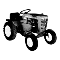
The Wheel Horse Rotary Mower, Model 5-1421, is designed to attach to various Wheel Horse tractors, specifically models 1056, 1046, 1076, 1276, 1057, 1257, 1077, 1277, 1067, 1267, Charger, and Raider. Its primary function is cutting grass. The mower utilizes a Power Take-Off (PTO) unit from the tractor for operation; an 8-3111 or PT-6 PTO is used for most listed models, while the 1046 model uses a PT-7. The mower features a deck with multiple blades, a height control mechanism, and an idler pulley system for belt tension.
Important Technical Specifications:
- Model: 5-1421
- Compatibility: Wheel Horse tractor models 1056, 1046, 1076, 1276, 1057, 1257, 1077, 1277, 1067, 1267, Charger, and Raider.
- PTO Unit: 8-3111 or PT-6 (for most models), PT-7 (for model 1046).
- Cutting Width: The parts list indicates a "Deck 42" Mower" (Ref. No. 1, Part No. 6690), suggesting a 42-inch cutting width. Service bulletins also mention "42" & 48" Rotary Mowers," confirming the 42-inch width for this model.
- Blades: The mower uses 14-inch blades (Ref. No. 18, Part No. 6693).
- Recommended Cutting Height: 2 to 3 inches.
- Recommended Mowing Speed: Full throttle, approximately 3½ M.P.H. For heavy or extra tall grass, it may be necessary to slow to ½ M.P.H.
- Spindle Assembly: The mower utilizes a spindle housing (Part No. 4299) with needle bearings (Part No. 1508), oil seals (Part No. 1303), and ball bearings (Part No. 1515). Service bulletins indicate that older spindle assemblies (like #5875 shaft) have been superseded by S/A 101686, which includes a shaft (104982), snap ring (104822), and washer (105819). The spindle housing #4299 or 8139 is no longer available, and older mowers can be converted to the latest greaseable type.
Usage Features:
- Installation:
- Wheels are installed to the mower, ensuring the side with the long hub extension goes against the gage wheel support, secured with shoulder bolts and jam nuts.
- The pivot arm assembly slides onto the mower support shaft and is secured with an "E" ring.
- The cam arm assembly (6727) is removed for future assembly.
- The lift rod (6699) attaches to the mower support from the right side of the lift rod plate, secured with a hairpin cotter (933504-4).
- The lift stud (6739) slides onto the lift rod and is secured with a 3/8-16 elastic stop nut.
- The right-hand mounting plate assembly attaches to the tractor frame, aligning specific holes and secured with a 3/8-16 x 1" bolt and a mounting plate support stud.
- The latch and shaft assembly (6710) must be positioned between the R.H. and L.H. plates with notches facing the rear of the tractor.
- The cam roller bushing (6714) mounts to the mounting plate support stud, held by an "E" ring (MW-4564).
- The tractor footrest is removed to slide on the cam arm assembly.
- To install the mower under the tractor, turn the tractor wheels all the way to the left, place mower wheels in the lowest cut position, then slide the mower under.
- Raise mower wheels to the highest cut position, attach lift stud (6739) to the end hole of the tractor lift lever (from the left side).
- Raise the mower with the lift lever until the cross shaft of the mower support fits into the mounting plate slots, then lock in place with the latch.
- A hairpin cotter (933512-4) is inserted into the front hole of the left-hand mounting plate to keep the latch in place.
- The cam arm assembly shaft slides through the pivot arm hole and is fastened with a hairpin cotter. The cam plate should ride in the cam roller bushing.
- The belt is threaded onto the pulley as shown on the belt decal on the cutter housing.
- Operation:
- To start the mower, push the clutch arm to the left to engage the clutch.
- To stop the mower, move the clutch arm to the right to disengage the clutch.
- For best cutting, operate at full throttle (approx. 3½ M.P.H.). For extra tall grass, raise the mower to travel position, cut, then recut at normal position, potentially slowing to ½ M.P.H.
- Do not cut grass too short; recommended height is 2 to 3 inches.
- Adjustments:
- Belt Tension: Loosen the bolt on the side of the cam plate and thread the belt tension nut in or out.
- Cutting Height: Raise the mower with the tractor lift lever to release weight from wheels. Lift the height control rod and rotate to the desired notch. Thread the nut down on the lift rod until the mower support is locked against the frame in the up position.
- Height Control Rods: Service bulletins indicate three types of height control rods (A, B, C). Early type A (6721) may interfere with late model tractor footrests and can be modified to type B or replaced with type C (7677) for better clearance.
- Belt Alignment (Electro Clutch Models): The electric clutch should be positioned on the crankshaft all the way against the shoulder in the clutch bore and secured with two set screws.
Maintenance Features:
- Blade Maintenance: For best results, remove the mower from the tractor. When blades are dull, remove and regrind them. Sharpen evenly on both ends to maintain balance. Inspect blades frequently (especially after hitting an object) and tighten the blade mounting bolt if necessary.
- Lubrication: Each blade spindle has a grease fitting visible through a hole in the top of the deck. Apply grease until it comes out of the blade cup. The unit should be greased every 50 hours of use with a regular lubricating pressure gun.
- Spindle Assembly: When building a complete spindle assembly from parts, fill the housing with 1-1/2 ounces of #2 multi-purpose lithium base grease.
- Mower Removal:
- Pull the hairpin cotter from the lift stud and drop the lift rod.
- Remove the belt from the Power Take-Off.
- Pull the hairpin cotter from the left-hand mounting plate and pull up on the latch to drop the mower support.
- Turn the tractor wheels to the left and pull the mower from under the tractor.
- Note: The hairpin cotter should be inserted through the rear hole in the L.H. Mtg plate to hold the latch up when the tractor is being operated without the mower.
Safety Tips:
- Read the owner's manual to know controls and how to stop quickly.
- Do not allow children or adults without proper instruction to operate the machine.
- Clear the work area of objects that might be picked up and thrown.
- Disengage all clutches and shift into neutral before starting the motor. Keep hands, feet, and clothing away from power-driven parts.
- Do NOT carry passengers; keep children and pets a safe distance away.
- Never direct discharge of material toward bystanders or allow anyone near the machine during operation.
- Disengage power to any attachment and stop the motor before leaving the operating position.
- Take precautions when leaving the machine unattended (avoid accidental starting, rolling away, dropping of attachments).
- Disengage power to attachments when not in use or when traveling between work areas.
- Stay alert for holes and other hidden hazards.
- Know what is behind you before backing up.
- Beware of steep slopes; reduce speed on side slopes and sharp turns to prevent tipping or losing control.
- Do not stop or start suddenly when going uphill or downhill.
- Use extra care when pulling loads or using heavy equipment (refer to owner's manual).
- Watch out for traffic when near roadways.
- Handle gasoline with care as it is highly flammable: use approved containers, never add gasoline to a running motor, fill the tank outdoors, wipe up spills, replace the cap securely. Open doors if the motor runs in a garage due to dangerous exhaust gases.
- Keep the machine in good operating condition and keep safety devices in place. Use guards as instructed in the owner's manual.
- Disengage power to any attachment and stop the motor before making repairs or adjustments.