P83566 P
Sheet 2 of 4
CAUTION: Strobes are not designed to be used on coded systems in which the applied voltage is cycled on and off.
WARNING: MAKE SURE THAT THE TOTAL RMS CURRENT REQUIRED BY ALL APPLIANCES THAT ARE CONNECTED TO THE
SYSTEM’S PRIMARY AND SECONDARY POWER SOURCES, NOTIFICATION APPLICIANCE CIRCUITS, SM, DSM SYNC MODULES, OR
WHEELOCK POWER SUPPLIES DOES NOT EXCEED THE POWER SOURCES’ RATED CAPACITY OR THE CURRENT RATINGS OF ANY FUSES
ON THE CIRCUITS TO WHICH THESE APPLIANCES ARE WIRED. OVERLOADING POWER SOURCES OR EXCEEDING FUSE RATINGS
COULD RESULT IN LOSS OF POWER AND FAILURE TO ALERT OCCUPANTS DURING AN EMERGENCY, WHICH COULD RESULT IN
PROPERTY DAMAGE AND SERIOUS INJURY OR DEATH TO YOU AND/OR OTHERS.
WIRING AND MOUNTING INFORMATION:
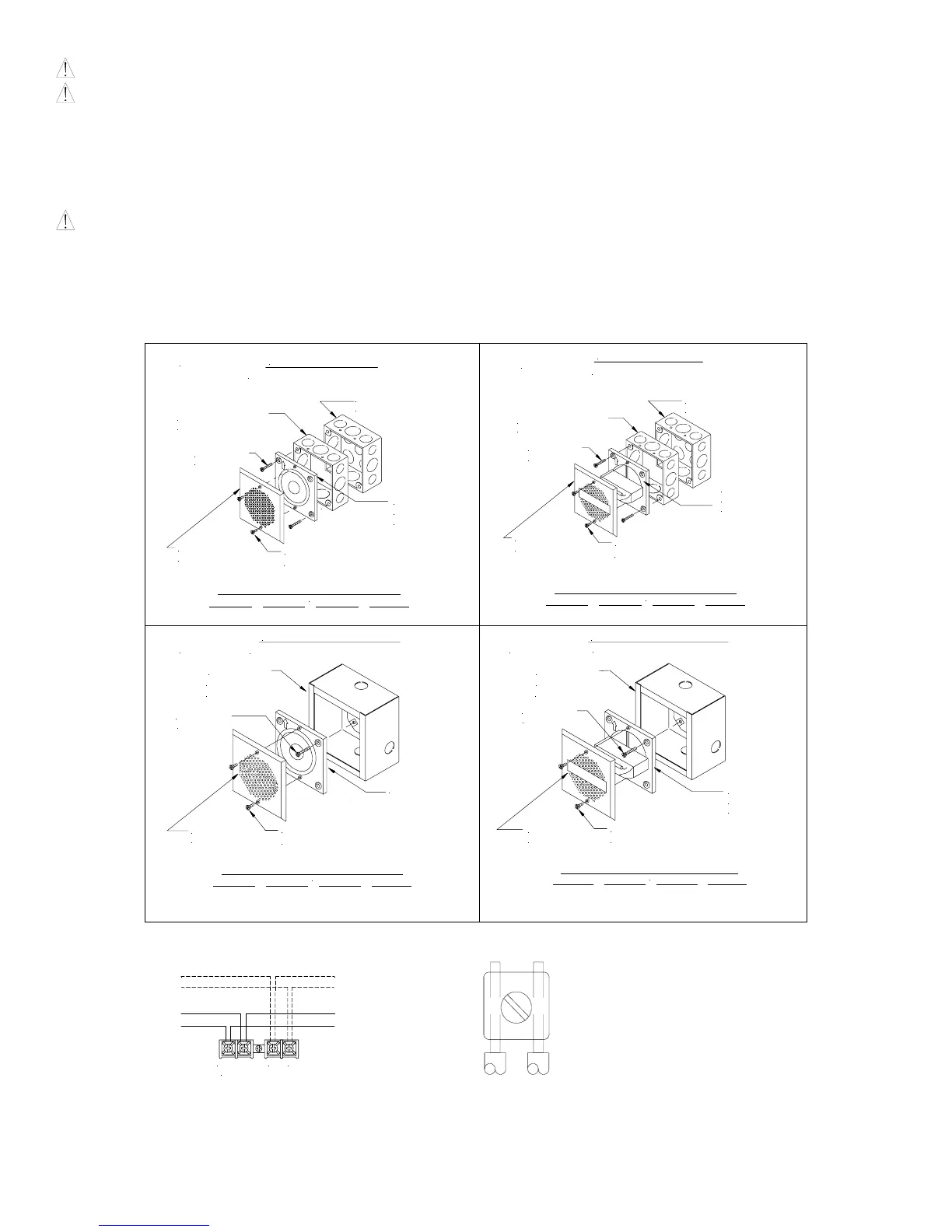
CAUTION: The following figures (A-D) show the maximum number of field wires (conductors) that can enter the backbox used with each mounting option. If
these limits are exceeded, there may be insufficient space in the backbox to accommodate the field wires and stresses from the wires could damage the product. Check
that the installed product will have sufficient clearance and wiring room prior to installing backboxes and conduit, especially if sheathed multiconductor cable or 3/4"
conduit fittings are used.
Although the limits shown for each mounting option comply with the National Electrical Code (NEC), Wheelock recommends use of the largest backbox option shown
and the use of approved stranded field wires, whenever possible, to provide additional wiring room for easy installation and minimum stress on the product from wiring.
NOTE: Surface backbox (SBB) in Figures C & D, is compatible with wiremold and conduit, mounting holes are for single-gang, double-gang, 4"sq., 3-1/2" & 4"
octagon or round backboxes.
4" SQ. X 1-1/2"
A
FLUSH MOUNTING
4" SQ. X 2-1/8"
BACKBOX
#8-32
SCREWS
EXTENSION RING *
#6-19
SCREWS
(NON-STROBE SPEAKER)
ROUND GRILLE
SQUARE OR
SPEAKER
MOUNTING
PLATE
MAXIMUM NUMBER OF CONDUCTORS
AWG #18 AWG #16 AWG #14 AWG#12
4 4 4 4
4" SQ. X 1-1/2"
B
FLUSH MOUNTING
4" SQ. X 2-1/8"
BACKBOX
#8-32
SCREWS
EXTENSION RING *
SCREWS
#6-19
ROUND GRILLE
SQUARE OR
(STROBE SPEAKER)
SPEAKER
MOUNTING
PLATE
MAXIMUM NUMBER OF CONDUCTORS
AWG #18 AWG #16 AWG #14 AWG#12
8 8 8 8
SURFACE MOUNTING
C
#8-32
SCREWS
BACKBOX
(SBB)
SURFACE
SPEAKER
MOUNTING
PLATE
SQUARE
SCREWS
#6-19
(NON-STROBE SPEAKER)
GRILLE
MAXIMUM NUMBER OF CONDUCTORS
AWG #18 AWG #16 AWG #14 AWG#12
4 4 4 4
MAXIMUM NUMBER OF CONDUCTORS
AWG #18 AWG #16 AWG #14 AWG#12
8 8 8 8
SURFACE MOUNTING
D
#8-32
SCREWS
BACKBOX
(SBB)
SURFACE
PLATE
MOUNTING
SPEAKER
SQUARE
GRILLE
SCREWS
#6-19
(STROBE SPEAKER)
NOTE: E90 has a round grille. E70 is shown.
Figure 1: Figure 2:
+ STROBE - COM+
(OPTIONAL)
FROM PRECEDING SPEAKER
OR FIRE ALARM
CONTROL PANEL (FACP)
FROM PRECEDING STROBE
APPLIANCE OR SYNC MODULE
TO NEXT APPLIANCE
OR EOLR
TO NEXT SPEAKER
OR END OF LINE RESISTOR
(EOLR)
• This model has in-out wiring terminals that accept two #12 to
#18 American Wire Gauge (AWG) wires at each screw terminal.
Strip leads 3/8 inches and connect to screw terminals.
• Break all in-out wire runs on supervised circuits to assure
integrity of circuit supervision as shown in Figure 2. The
polarity shown in the wiring diagrams is for operation of the
appliances.
* Refer to Sync Module instruction sheets SM (P83123), DSM (P83177) or Wheelock Power Supplies for additional information.
GROUNDING: Connect ground wire to backbox. Install signaling appliance to backbox using mounting screws provided.
 Loading...