P83566 P
Sheet 3 of 4
WARNING: CHECK ELECTRICAL RATINGS SPECIFIED IN TABLES 1 AND 2 (AS APPROPRIATE) TO ENSURE PROPER INPUT. BE SURE
THAT SPEAKER WIRING IS CONNECTED TO SPEAKER TERMINALS ONLY AND STROBE WIRING IS CONNECTED TO STROBE TERMINALS
ONLY. CHECK TO INSURE THAT WIRING AT FACP IS CORRECT. IMPROPER ELECTRICAL INPUT CAN DAMAGE THE PRODUCT OR
CAUSE IT TO MALFUNCTION, WHICH COULD RESULT IN PROPERTY DAMAGE AND SERIOUS INJURY OR DEATH TO YOU AND/OR
OTHERS.
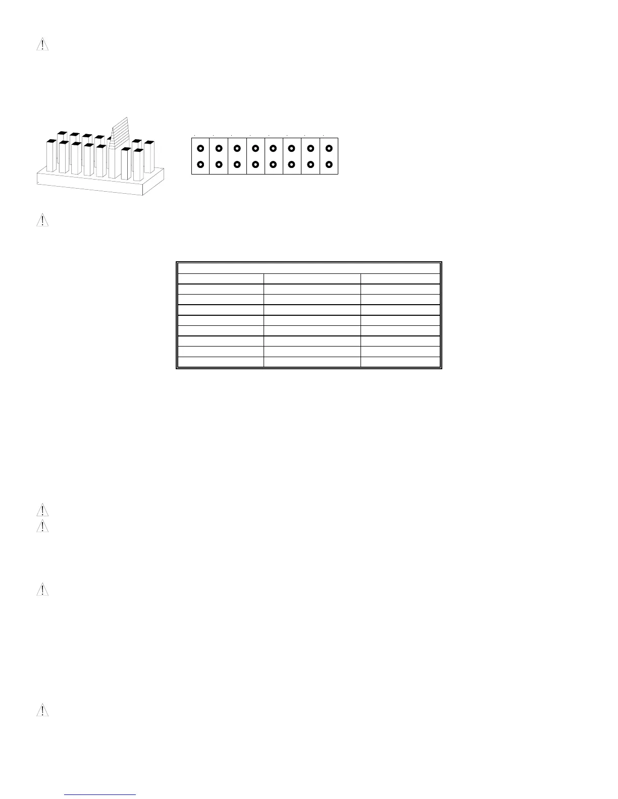
Figure 3: Jumper plug is used to select tap
settings which = dBA loudness.
Figure 4: Tap Settings (Factory setting is 70V @
1/2W (Tap F))
A
B
C
D
E
F
G
H
B
D E
G H
1. Each doubling of rated Watts increases sound output by 3 dBA.
Field selectable input terminals are provided on each unit. The
following wattage selections are available: 1/8W, 1/4W, 1/2W,
1W and 2W.
2. Each letter corresponds to a plug position of the header located
on the printed circuit board. Select voltage and wattage as
shown in Table 3 below.
3. A 1.5µF blocking capacitor for DC supervision of audio lines
by the FACP is factory wired in series with the speaker input.
NOTE: Use needle nose pliers to pull and properly insert the jumper plug to the desired tap setting.
WARNING: THE SPEAKER STROBE APPLIANCE MUST BE FIELD SET TO THE DESIRED dBA SOUND OUTPUT LEVEL BEFORE IT IS
INSTALLED. THIS IS DONE BY PROPERLY INSERTING JUMPER PLUGS IN ACCORDANCE WITH THESE INSTRUCTIONS. INCORRECT
SETTINGS WILL RESULT IN IMPROPER PERFORMANCE, WHICH COULD RESULT IN PROPERTY DAMAGE AND SERIOUS INJURY OR
DEATH TO YOU AND/OR OTHERS.
Table 3: Speaker Voltage and Wattage Connection Chart
Position 25V 70V
A 2 ------
B 1 ------
C 1/2 ------
D 1/4 2
E 1/8 1
F ------ 1/2
G ------ 1/4
H ------ 1/8
MOUNTING PROCEDURES:
1. These models can be flush mounted to a 4” square by 2-1/8” deep backbox with a 4” square 1-1/2” extension ring (Figure A) or surface mounted to a surface
backbox (Figure B). Mounting hardware for each mounting option is supplied.
2. Conduit entrances to the backbox should be selected to provide sufficient wiring clearance for the installed product. Do not pass additional wires (used for other
than the signaling appliance) through the backbox. Such additional wires could result in insufficient wiring space for the signaling appliance.
3. When terminating field wires, do not use more lead length than required. Excess lead length could result in insufficient wiring space for the signaling appliance.
4. Use care and proper techniques to position the field wires in the backbox so that they use minimum space and produce minimum stress on the product. This is
especially important for stiff, heavy gauge wires and wires with thick insulation or sheathing.
5. These models have an integrated speaker mounting plate which must be oriented correctly when it is mounted to the backbox. Turn the speaker mounting plate
so that the arrow above the words “Horizontal Strobe” points to the top side of the speaker mounting plate.
6. Mount the speaker mounting plate to the backbox. Next slide the grille over the speaker mounting plate strobe and attach with (2) screws.
WARNING: THE E70/90 SPEAKER STROBE APPLIANCE IS A "FIRE ALARM DEVICE - DO NOT PAINT."
WARNING: WHEN INSTALLING STROBES IN AN OPEN OFFICE OR OTHER AREAS CONTAINING PARTITIONS OR OTHER VIEWING
OBSTRUCTIONS, SPECIAL ATTENTION SHOULD BE GIVEN TO THE LOCATION OF THE STROBES SO THAT THEIR OPERATING EFFECT
CAN BE SEEN BY ALL INTENDED VIEWERS, WITH THE INTENSITY, NUMBER, AND TYPE OF STROBES BEING SUFFICIENT TO MAKE SURE
THAT THE INTENDED VIEWER IS ALERTED BY PROPER ILLUMINATION, REGARDLESS OF THE VIEWER'S ORIENTATION. FAILURE TO
DO SO COULD RESULT IN PROPERTY DAMAGE AND SERIOUS INJURY OR DEATH TO YOU AND/OR OTHERS.
WARNING: A SMALL POSSIBILITY EXISTS THAT THE USE OF MULTIPLE STROBES WITHIN A PERSON'S FIELD OF VIEW, UNDER
CERTAIN CIRCUMSTANCES, MIGHT INDUCE A PHOTO-SENSITIVE RESPONSE IN PERSONS WITH EPILEPSY. STROBE REFLECTIONS IN A
GLASS OR MIRRORED SURFACE MIGHT ALSO INDUCE SUCH A RESPONSE. TO MINIMIZE THIS POSSIBLE HAZARD, WHEELOCK
STRONGLY RECOMMENDS THAT THE STROBES INSTALLED SHOULD NOT PRESENT A COMPOSITE FLASH RATE IN THE FIELD OF VIEW
WHICH EXCEEDS FIVE (5) Hz AT THE OPERATING VOLTAGE OF THE STROBES. WHEELOCK ALSO STRONGLY RECOMMENDS THAT THE
INTENSITY AND COMPOSITE FLASH RATE OF INSTALLED STROBES COMPLY WITH LEVELS ESTABLISHED BY APPLICABLE LAWS,
STANDARDS, REGULATIONS, CODES AND GUIDELINES.
If this appliance is required to produce a distinctive three-pulse Temporal Pattern Fire Alarm Evacuation Signal (for total evacuation) in accordance with NFPA 72, the
appliance must be used with a fire alarm control unit that can generate the temporal pattern signal. Refer to manufacturer’s installation manual for details.
NOTE: NFPA 72/ANSI 117.1 conforms to ADAAG Equivalent Facilitation Guidelines in using fewer, higher intensity strobes within the same protected area.
CAUTION: Check the installation instructions of the manufacturers of other equipment used in the system for any guidelines or restrictions on wiring and/or
locating Notification Appliance Circuits (NAC) and notification appliances. Some system communication circuits and/or audio circuits, for example, may require
special precautions to assure electrical noise immunity (e.g. audio crosstalk).
 Loading...