EasyManua.ls Logo

Whelen Engineering Company 295SLS Series User Manual

Whelen Engineering Company 295SLS Series
6 pages
To Next Page IconTo Next Page
Page #1 background imageLoading...
Page #1 background image
Page 1
Installation Guide:
295SLS*6 Siren Amplifier
©2008 Whelen Engineering Company Inc.
Form No.14130E (031610)
®
ENGINEERING COMPANY INC.
Automotive: Sirens/Switches
Safety First
This document provides all the necessary information to allow your Whelen product to be properly and safely installed.
Before beginning the installation and/or operation of your new product, the installation technician and operator must
read this manual completely. Important information is contained herein that could prevent serious injury or damage.
Proper installation of this product requires the installer to have a good understanding of automotive electronics,
systems and procedures.
Failure to use specified installation parts and/or hardware will void the product warranty!
If mounting this product requires drilling holes, the installer MUST be sure that no vehicle components or other
vital parts could be damaged by the drilling process. Check both sides of the mounting surface before drilling
begins. Also de-burr any holes and remove any metal shards or remnants. Install grommets into all wire
passage holes.
If this manual states that this product may be mounted with suction cups, magnets, tape or Velcro®, clean the
mounting surface with a 50/50 mix of isopropyl alcohol and water and dry thoroughly.
Do not install this product or route any wires in the deployment area of your air bag. Equipment mounted or
located in the air bag deployment area will damage or reduce the effectiveness of the air bag, or become a
projectile that could cause serious personal injury or death. Refer to your vehicle owners manual for the air bag
deployment area. The User/Installer assumes full responsibility to determine proper mounting location, based
on providing ultimate safety to all passengers inside the vehicle.
For this product to operate at optimum efficiency, a good electrical connection to chassis ground must be
made. The recommended procedure requires the product ground wire to be connected directly to the NEGATIVE
(-) battery post.
If this product uses a remote device to activate or control this product, make sure this control is located in an
area that allows both the vehicle and the control to be operated safely in any driving condition. DO NOT
ATTEMPT TO ACTIVATE OR CONTROL THIS DEVICE IN A HAZARDOUS DRIVING SITUATION.
It is recommended that these instructions be stored in a safe place and
referred to when performing maintenance and/or reinstallation of this
product.
FAILURE TO FOLLOW THESE SAFETY PRECAUTIONS AND
INSTRUCTIONS COULD RESULT IN DAMAGE TO THE PRODUCT OR
VEHICLE AND/OR SERIOUS INJURY TO YOU AND YOUR PASSENGERS!
DANGER! Sirens produce extremely loud emergency warning tones! Exposure to these tones without
proper and adequate hearing protection, could cause ear damage and/or hearing loss! The Occupational Safety &
Health Administration (www.osha.gov) provides information necessary to determine safe exposure times in
Occupational Noise Exposure Section 1910.95. Until you have determined the safe exposure times for your
specific application, operators and anyone else in the immediate vicinity should be required to wear an approved
hearing protection device. FAILURE TO FOLLOW THIS RECOMMENDATION COULD CAUSE HEARING LOSS!
CAUTION
Loud siren noise can cause
hearing damage and/or loss.
Refer to OSHA Section 1910.95 prior
to putting ANY siren into service!
Wear
Protection!
ACTIVATION OF THIS
SIREN MAY DAMAGE
UNPROTECTED EARS!
51 Winthrop Road
Chester, Connecticut 06412-0684
Phone: (860) 526-9504
Fax: (860) 526-4078
Internet: www.whelen.com
Sales e-mail: autosale@whelen.com
Canadian Sales e-mail: canadiansales@whelen.com
Customer Service e-mail: custserv@whelen.com
For warranty information regarding this product, visit www.whelen.com/warranty
Question and Answer IconNeed help?

Do you have a question about the Whelen Engineering Company 295SLS Series and is the answer not in the manual?

Whelen Engineering Company 295SLS Series Specifications

General IconGeneral
BrandWhelen Engineering Company
Model295SLS Series
CategoryAmplifier
LanguageEnglish

Summary

Mounting Procedures

Bail Strap Mounting

Instructions for mounting the siren using a bail strap bracket.

Console Mounting

Guidance on mounting the siren into a vehicle's console.

Microphone Clip Installation

Information regarding the installation of the included microphone clip.

Wiring Connections

Siren Power and Ground Wiring

Details for connecting the RED (power) and BLACK (ground) wires.

Speaker Wiring (Orange, Yellow, Brown)

Instructions for connecting the ORANGE, YELLOW, and BROWN speaker wires.

Siren Interruption Wiring (Violet)

Explains the VIOLET wire for siren interruption control.

Additional Wiring and Input Connectors

3-Position Input Connector Details

Details on the 3-position input connector for Aux Enable and Siren In Use.

Main Power Wire Connections (10 AWG)

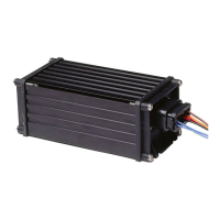
Instructions for connecting the 10 AWG RED power wires to the battery.

Front Panel Controls and Features

Power Switch Operation

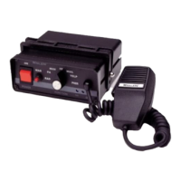
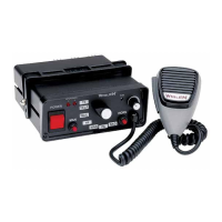
Explains the function of the main power switch.

Rotary Switch Functions

Details the 7 positions of the rotary switch for siren control.

Volume Knob Adjustment

How to adjust the Public Address function volume.

Radio Repeat Volume Setting

Procedure for setting the Radio Repeat output volume.

MAN Button Operation

Describes the function of the manual activation button.

SI TEST and Diagnostic Indicators

Information on the SI TEST feature and diagnostic indicator meanings.

Horn Button Functionality

Operation of the horn button for generating the AIRHORN tone.

Programmable Power Switch Overview

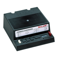
Overview of the programmable power distribution switches.

Microphone Usage

How to use the microphone for Public Address function.

Rotary Switch Operation Modes

RAD Mode: Radio Repeat

Operation when the rotary knob is in the RAD position for radio rebroadcast.

MAN 1 Mode: Manual Siren #1

Operation in MAN 1 mode for manual siren activation.

MAN 2 Mode: Manual Siren #2

Operation in MAN 2 mode for manual siren activation.

HF Mode: Hands-Free Operation

Operation in HF mode for hands-free siren tone cycling.

T1 Mode: Tone #1 (WAIL)

Operation in T1 mode for the WAIL tone.

T2 Mode: Tone #2 (YELP)

Operation in T2 mode for the YELP tone.

T3 Mode: Tone #3 (Fast Rise/Fall)

Operation in T3 mode for a fast rise and fall tone.

Terminal Block and Fuse Configuration

Terminal Specifications and Load Limits

Details on terminal specifications and maximum load ratings.

Custom Fuse Configurations for Aux Circuits

How to configure fuses for auxiliary circuit control.

Siren Programming Procedures

Programming Power Distribution Outputs

Procedure to program switch outputs for power distribution.

Programming Switch Types

How to configure the type of operation for the lighting control switches.

Siren Tone Customization

Steps to customize the siren's tones and override tones.

Advanced Siren Configuration

Copying Unit Configuration

Method for copying a siren's configuration to another unit.

Title 13 Operation Mode

Instructions to put the siren into Title 13 operation mode.

Power Switch Configuration Options

Configuring power distribution switches to operate with the main power switch.

Resetting Factory Defaults

Procedure to restore siren tones and configurations to factory defaults.

Siren Interruption Mode Configuration

Configuring the siren interruption feature (PAUSE or CANCEL modes).

Circuit Board Access and System Specifications

Accessing the Circuit Board

Steps to access the siren's circuit board for maintenance.

System Specifications

Technical specifications for the siren amplifier unit.

Related product manuals