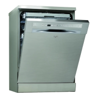
Do you have a question about the Whirlpool 6ADP2956 IXM and is the answer not in the manual?
Covers physical dimensions, decor plate details, circuit boards, programmes, alarms, and options.
Details electrical specifications, motor data, water pressure, and flow rates.
Information on heating, water valves, dispenser coil, NTC sensor, and related components.
Quantities of water used in cycles, measuring levels, detergent limits, and motor speeds.
Exploded view and part identification for the dishwasher cabinet assembly.
Exploded view and part identification for the dishwasher door and control panel assembly.
Detailed list of spare parts with item, part numbers, and descriptions.
Continuation of spare parts list with item, part numbers, and descriptions.
Further continuation of spare parts list with item, part numbers, and descriptions.
Final part of spare parts list with item, part numbers, and descriptions.
Detailed breakdown of dishwasher program sequences and their operational steps.
Schematic diagram of the dishwasher's electrical system and component identification.
Steps to initiate and run the passive test programme for diagnostics.
Lists failure codes (F0-F9) and their corresponding indications during testing.
Outlines the procedure for diagnosing faults using the service test programme.
Elaborates on the passive test process, including notes on repair and reset.
Diagnosis for sensor and NTC failures, including causes and indications.
Diagnosis for water leakage, heating, and drainage system defects.
Diagnosis for water control, flow meter, and water level errors.
Steps to initiate the active test and its operational flow.
Important notes regarding test programme behavior, fault storage, and exit conditions.
Explanation of Zone Wash Valve operation during the test programme.
Guides on required probes, safety precautions, and identifying test points.
Voltage measurements for push button communication with the display board.
Voltage measurements for rotary switch communication with the user board.
Voltage measurements for start button communication with the display board.
| Brand | Whirlpool |
|---|---|
| Model | 6ADP2956 IXM |
| Category | Dishwasher |
| Language | English |






 Loading...