EasyManua.ls Logo

Whirlpool AWT 2284 User Manual

Whirlpool AWT 2284
9 pages
To Next Page IconTo Next Page
Page #1 background imageLoading...
Page #1 background image
SERVICE
Whirlpool Europe
Customer Services
Model AWT 2284
Version 8561 228 10140 Page
Technical data 2 - 3
Spare part list 4
Exploded view 5 - 6
Wiring diagram 7
Circuit diagram 8
Program diagram 9
Service Manual
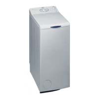
Washing machine
Toploader
AWT 2284
AWT 2284
This documentation is only intended for qualified technicians who are aware of the respec-
tive safety regulations.
Date: 21.05.2001 Subject to modification
Document-No.: 4812 712 16287
Question and Answer IconNeed help?

Do you have a question about the Whirlpool AWT 2284 and is the answer not in the manual?

Whirlpool AWT 2284 Specifications

General IconGeneral
BrandWhirlpool
ModelAWT 2284
CategoryWasher
LanguageEnglish

Summary

Technical Data

Dimensions, Weight, and Electrical Connections

Physical dimensions, weight, and main electrical connection specifications.

Drum, Laundry Capacity, and Water Level

Drum volume, dry laundry capacity, spin speeds, and pressostat levels.

Key Component Specifications

Data for door lock, heating element, water valve, and drain pump.

Thermostats, Motor, and Controls

Specifications for thermostats, motor, program timer, and speed selectors.

Spare Part List

Major Components and Assemblies

List of main structural and functional parts like doors, panels, drum, and motor.

Small Parts and Fasteners

Includes seals, clamps, screws, springs, and bearings for repairs.

Exploded View

Main Body and Outer Panels

Exploded diagrams of the outer casing, door frame, and base components.

Internal Drum and Motor Assembly

Exploded views of the drum, motor, belt, and related internal parts.

Control Panel and Electrical Components

Exploded diagrams of the control panel, buttons, and wiring connectors.

Wiring Diagram

Terminal Positions and Connectors Overview

Identification of terminal positions and connector types (XC1-XC4).

Component Wiring Logic and Abbreviations

Detailed electrical connections and key for component abbreviations.

Circuit Diagram

Main Power and Control Circuit Schematic

Schematic of the primary electrical flow and control logic.

Component Connections and Safety Logic

Detailed circuit layout for motor, heating, pumps, and safety interlocks.

Selector Switch and Timer Connections

Specific circuit connections for the spin speed selector and program timer.

Program Diagram

Washing Cycle Timing Chart

Detailed timing for various wash programs, including water level and heating phases.

Program Step Activity Breakdown

Chart showing component activities (valve, pump, motor) per program step.

Wash Program Options and Variations

Overview of options like half load, rinse stop, and intensive rinse.

Related product manuals