Do you have a question about the Whirlpool MH6140XKQ/B and is the answer not in the manual?
Key safety messages and precautions for handling the microwave oven and preventing electrical shock.
Guidance on preventing damage to electronic components from static discharge during servicing.
Illustrates and explains the three possible mounting positions for the vent motor.
Explains the function and location of the oven thermostat and vent motor capacitor.
Describes the function and operation of the vent motor and turntable motor.
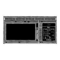
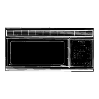
Diagram showing the internal locations of major components within the microwave oven.
Step-by-step instructions for safely removing the turntable motor and cooktop lamp assembly.
Detailed procedure for removing the control panel and its associated electronic control board.
Instructions for safely disconnecting and removing the primary, secondary, and monitor door interlock switches.
Step-by-step guide for removing the oven's internal lamp assembly.
Procedure for removing the oven thermostat, line fuse holder, and power cord.
Instructions for removing the vent motor capacitor, high voltage capacitor, and high voltage rectifier.
Step-by-step guide for safely removing the high voltage transformer.
Procedure for safely removing the magnetron component from the microwave oven.
Instructions for safely removing the vent motor assembly from the microwave oven.
Detailed steps for removing the oven door, its internal switch actuators, and the outer glass panel.
Procedure for testing the continuity of the touch panel using an ohmmeter.
Instructions for testing the electrical resistance of the turntable and vent motors.
Procedures for testing the vent motor capacitor, line fuse, oven thermostat, and door switches.
Steps for testing the high voltage capacitor and the high voltage rectifier (diode).
Procedures for testing the primary and secondary windings of the high voltage transformer.
Instructions for testing the magnetron's filament resistance and case-to-filament resistance.
Comprehensive wiring diagram illustrating the electrical connections of the microwave oven components.
Illustrates various operational modes and their corresponding electrical strip circuits.
| Power | 1000 Watts |
|---|---|
| Color | Black |
| Installation | Countertop |
| Preset Cooking Programs | Yes |
| Child Lock | Yes |
| Defrost Function | Yes |
| Display Type | Digital |
| Voltage | 120V |
| Frequency | 60 Hz |
| Control Type | Electronic |
| Weight | 36 lbs |