TYPE 124
To prevent electrical shock
and/or equipment damage, dis-
connect electric power to sys-
tem at main fuse or circuit
breaker box until installation
is complete.
WARNING
!
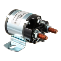
Fig. 1
Single Pole Normally Open (Isolated Coil)
Interrupteur Unipolaire De Travail (Bobine Isolée)
Unipolar Normalmente Abierto (Bobina Separada)
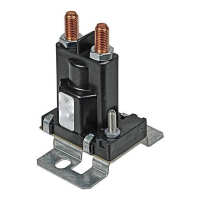
Fig. 2
Single Pole Double Throw (Isolated Coil)
Commutateur Unipolaire (Bobine Isolée)
Unipolar Normalmente Abierto (Bobina Separada)
WHITE-RODGERS DIVISION
EMERSON ELECTRIC CO.
9797 REAVIS ROAD
ST. LOUIS, MISSOURI 63123-5398
www.white-rodgers.com
PART NO./No. DE PIÈCE/No. DE PARTE 37-6348A
0152
Pour éviter les risques
d’électrocution et/ou de dégâts
de l’équipement, il faut
débrancher l’alimentation
électrique du système au fus-
ible ou au coupe-circuit prin-
cipal jusqu’à la fin de
l’intervention.
Para evitar el choque eléctrico
y/o el daño en el equipo,
desconecte la energía eléctrica
que va al sistema en el fusible
principal o en la caja de
interruptores de circuito, hasta
que se haya completado la
instalación.
WARNING
!
WARNING
!
A
Wiring Diagram (Terminal Identification)
B
Coil
C
N.O. Contacts
D
N.C. Contacts
D.C. POWER CONTACTOR
SERVICE INSTRUCTIONS
CONTACTEUR C.C.
INSTRUCTIONS D'ENTRETIEN
CONTACTOR CON ENERGÍA DE
CORRIENTE CONTINUA
INSTRUCCIONES DE SERVICIO
A
B
B
CC
A
B
B
C C
D D
A
Diagrama De Cableado (Identificación De
Terminales)
B
Bobina
C
Contactos Normalmente Abiertos
D
Contactos Normalmente Cerrados
A
Schéma De Câblage (Identification Des
Bornes)
B
Bobine
C
Contacts De Travail
D
Contacts De Repos
Voltage
(VDC Max.)
Contact
Contact
Contacto
Duty Cycle / Cycle de service / Ciclos de Servicio
Continuous / Continu / Continuo
Continuous / Continu / Continuo
Continuous / Continu / Continuo
Continuous / Continu / Continuo
Continuous / Continu / Continuo
Coil
Bobine
Bobina
Tension
(Vc.c. maxi.)
Voltage
(VDC max.)
124-105111
124-104111
124-117111
124-314111
124-317111
12
24
36
24
36
12
24
36
24
36
SPECIFICATIONS:
Insulated Coil Terminals
Preferred Mounting Position–Coil
Terminals Up
CARACTÉRISTIQUES:
Bornes Isolées De Bobine
Position De Montage Privilégiée -
Bornes De Bobine Excitées
ESPECIFICACIONES:
Terminales De La Bobina Aislados
Posición De Montaje Preferida -
Terminales De La Bobina Arriba