1. Package Contents
Installation Guide
www.witek-iiot.com
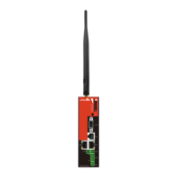
Industrial M2M LTE Gateway
WI-IOT110
LAN 1
RS2 32
LAN 2
GPI O1
GND
A
B
VCC
PWR
RS4 85
GPI O2
WAN
RST
RS2 32
WAN
LAN 2
LAN 1
RS4 85
PWR
WI-IOT110
1 x AC Power Adapter
2 x WiFi Antennas 2 x 4G Antenna
1 x DIN-rail installation kit
1 x 4 PinTerminal 3 x 2 Pin Terminal
4. Network Application
Flexible Power Option
A. Power by WAN PoE In
LAN 1
RS2 32
LAN 2
GPI O1
GND
A
B
VCC
PWR
RS4 85
GPI O2
WAN
RST
RS2 32
WAN
LAN 2
LAN 1
RS4 85
PWR
WI-IO T110
Serial Port RS-232
WAN/PoE In
LAN2/PoE Out
LAN1/PoE Out
DI/DO Terminal
Serial Port RS-485
Reset
SIM Holder
Control Center
VPN
4G LTE
B. Power by 12-60V DC in
LAN 1
RS2 32
LAN 2
GPI O1
GND
A
B
VCC
PWR
RS4 85
GPI O2
WAN
RST
RS2 32
WAN
LAN 2
LAN 1
RS4 85
PWR
WI-IO T110
Serial Port RS-232
WAN
LAN2/PoE Out
LAN1/PoE Out
DI/DO Terminal
Serial Port RS-485
Reset
SIM Holder
Control Center
VPN
4G LTE
Power Terminal Block
PoE In
Waterproof Power adapter
*
No
t In
c
l
u
d
e
d p
a
c
k
i
n
g b
o
x
1
1
0
-
2
4
0
V
PO
W
E
R
S
U
PP
LY
4
8
V-
54
V
PO
WE R SUP PLY
12V-
60V
3. Mounting
Mounting the switch on a DIN rail
As shown in Figure position the switch so that the spring of the DIN rail mounting bracket
compresses against the upper edge of the DIN rail.
1
2
5. Login Method
LAN1
RS232
LAN2
GPIO1
GND
A
B
VCC
PWR
RS485
GPIO2
WAN
RST
RS232
WAN
LAN2
LAN1
RS485
PWR
WI- IOT110
Failover Failback
ADS L / Fiber / Cable
4G LTE
Wireless Connecti on
Internet
Backup
Primary
Wireline Connecti on
PC
PC
1
10
-2
4
0
V
POW
E
R
S
U
P
P
L
Y
48V-5
4
V
P
O
W
ER
S
U
PP
L
Y
12
V-
60V
Please connect devices according to the above topology.
Follow the steps for quick Gateway configuration, using initial setup wizard:
Connect your PC to device via Ethernet or wireless.Step 1
Step 2 Launch your web browser then enter http://192.168.10.1 in the address bar and specify
the default login key:root/12345678.
Note:
Default WiFi name: IIoT-xxxxxx, Password: 88888888
Step 4 Clink Device templates, Edit DTDL to get dtmi.
Username
Address
Telephone No.
Purchase Shop
Purchase Address
Product Model No.
Purchase Time
Serial No.
Dealer Signature
If the product defects within three months after purchase, we will provide you a new
product of the same model.
If the product defects within the three-year warranty period, we will provide the
professional maintenance service.
Proof of purchase and a complete product serial number are required to receive any
ser vices guaranteed as part of the limited warranty.
Any other defects that are not caused by workmanship or product quality, such as
natural disaster, water damage, extreme thermal or environmental conditions. sticker
damaged, warranty card losing will disqualify the product from limited warranty.
Warranty Card
RoHS
Technical Support
WIRELESS-TEK TECHNOLOGY LIMITED
Address: Biaofang Technology Building 402, Bao'an street,
Baoan District,Shenzhen City, Guangdong, China
Website: www.witek-iiot.com
Tel:86-0755-32811290
Email: sales@witek-iiot.com
Design Industrial IoT for Smarter and More Connected
Company Website
Installation Guide
www.witek-iiot.com
Industrial M2M LTE Gateway
WI-IOT110
6.1 Click Quickstart, General, select Timezone or click Sync with browser, select Internet Mode
Priority, WAN Mode and Cloud, and then click Next to enter.
6.2 Configure WiFi SSID and WiFi Key, and then click Next to enter.
6. Quickstart Configuration Steps
6.4 If you need to configure 4G information, you can configure them. If you do not need
to directly click Next.
6.5 Configure WAN Mode, you can configure them. If you do not need to directly click Next.
6.3 Configure IP Address, Net Mask and DNS, and then click Next to enter.
7. Cloud Management Settings
7.1 Click Cloud-IoT and Enable Azure.
7.2 Fill in the Scope ID, Device ID, Device Key and DTMI
7.3 Select the content you want to upload, and then Click Save & Apply.
Step 1 Launch your web browser then enter https://login.microsoftonline.com/
in the address bar.
Log in to the cloud account with the account password after registration. Step 2
Click Connect and to get Scope ID, Device ID, key.Step 3
Here are the steps to get the above information from Microsoft Azure.
6.7 Waiting device reboot.
6.6 If you need to configure Azure-Cloud or Amazon-Cloud, you can configure them. If you do
not need to directly click Finish.
2. Hardware Introduction
2.1 Front Panel
2.2 Top Panel
LAN 1
RS2 32
LAN 2
GPI O1
GND
A
B
VCC
PWR
RS4 85
GPI O2
WAN
RST
RS2 32
WAN
LAN 2
LAN 1
RS4 85
PWR
WI-IOT110
Serial Port RS-232
WAN/PoE In
LAN2/PoE Out
LAN1/PoE Out
DI/DO Terminal
Serial Port RS-485
Power Terminal Block
Reset
SIM Holder
WiFi 4G 4G WiFi
Attention: DI(0~3V), if the voltage is too high, it may burn out the gateway.
LED Indicators
Status
Descripcation
LED Indicators
On
Power on
Off
Power off
RS232
Blink
Data reception
Off
No Data recption
LAN1&LAN2&
WAN
On
Link established
Off
No link
4G
Five lights are on
N/A
Four lights are on
RSSI>-85dBm;
SINR>25
Three lights are on
RSSI=
-85~-95dBm;
SINR: 15-25
Two lights are on
RSSI=
-95~-105dBm;
SINR: 11-14
one light are on
RSSI=
-105~-115dBm;
SINR: ≤10
RS485
On
Link esablished
Off
No Iink