1 2 5
Power
sensor
6 7
8
3 4
cool
heat
alarm
ON
lock
Power
①
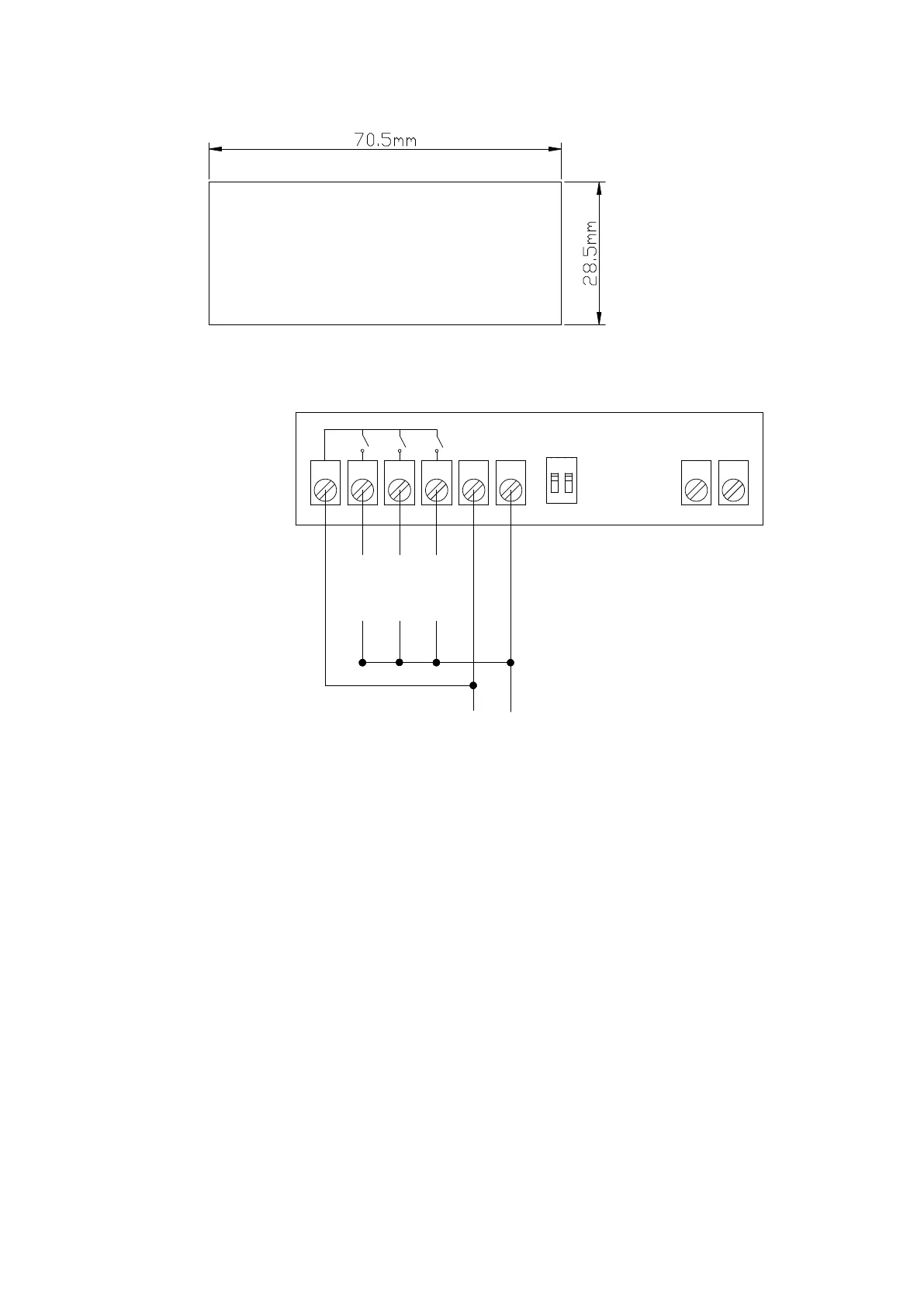
Installation opening size:
②
Wiring diagram:
Terminals 1 and 2: Connect the cooler
Terminals 1 and 3: Connect the heat
Terminals 1 and 4: Connect the alarm
Terminals 5 and 6: Connect the power
Terminals 7 and 8: Connect temperature sensor
Lock switch:
Switch either “1” or “2” to “ON”, press “SET” 3 seconds to disable the advance
model, user only can change temperature but can't reset the system
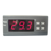
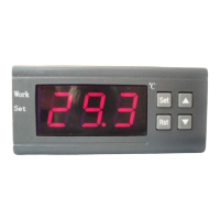
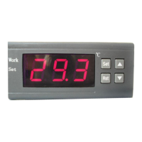
◆LED Status Description:
The WORK light is used as working indicator lights, flashing is to indicate the
delay of cooling or heating, if the LED is always on, it indicates it is on the
status of cooling or heating .
The SET light is used as setting indicator lights, if the LED is always on, it
indicates it is on the status of setting.