96 & 97 LED SERIES
INSTALLATION INSTRUCTIONS
H.E. Williams, Inc. Carthage, Missouri www.hew.com 417-358-4065
Information contained herein is subject to change without notice.
PN #49090174
Page 2 of 2
REV.12/20/23.JL
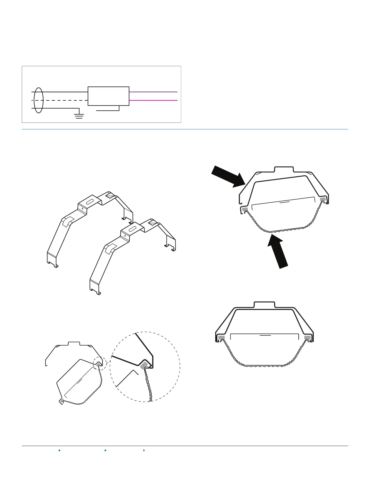
WIRING DIAGRAM
Purple (DIM +)
Pink or Gray (DIM -)
0-10v Dimming driver leads.
Refer to the dimming driver
instructions, if needed.
Black (Line)
White (Neutral)
Ground
LED Driver(s)
Driver/power supply disconnects accept #12 – #16 AWG stranded or solid wire.
Attach power supply and ground wires using UL listed wire connectors.
Please consult factory for other driver configurations or emergency driver wiring diagrams.
Ground wire
if needed
Supply
INSTALLATION
Step 1: Securely attach mounting brackets (2) to mounting surface.
The 96/97 enclosure will engage the mounting brackets at
any point along itslength, except for where there are latches.
Required spacing between the brackets are as follows: 12″ - 17″
for 2′ housings, 30″ - 42″ for 4′ housings, and 48″- 80″ for 8′
housings.
FIG 1.1
Step 2: Insert one side of the 96/97 housing into the mounting
brackets.
FIG 2.1
Step 3: Push up on the enclosure and then press in on the mounting
bracket until the mounting bracket clicks into place.
FIG 3.1
Step 4: Verify that the enclosure is fully supported before connecting
to a power supply.
FIG 4.1
 Loading...