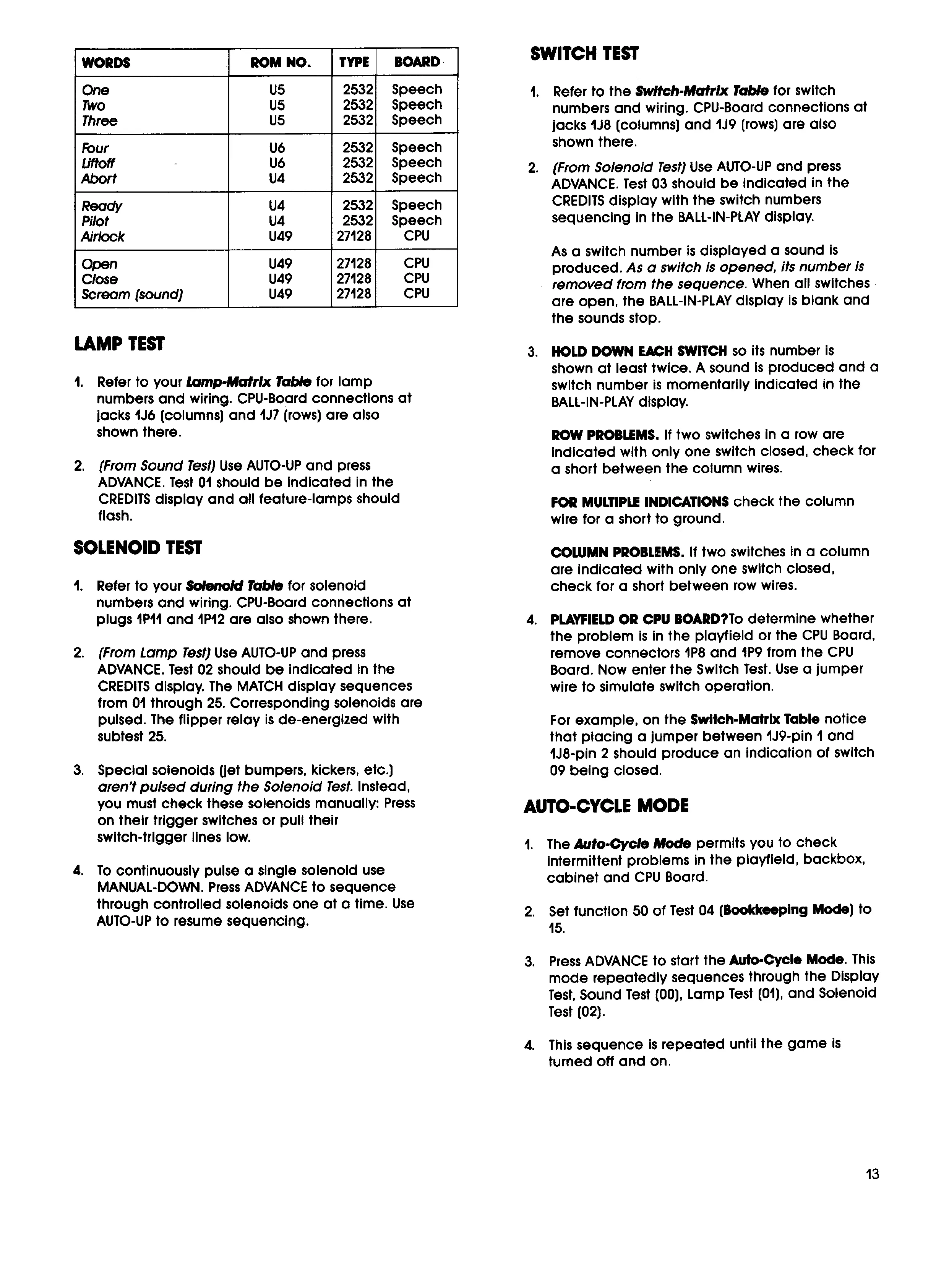
WORDS
ROM NO.
TYPE
BOARD
One
U5
2532
Speech
Two
U5
2532
Speech
Three
US
2532
Speech
Four
U6
2532
Speech
Liftoff
-
tJ6
2532
Speech
Abort
U4
2532
Speech
Ready
U4
2532
Speech
Pilot
U4
2532
Speech
Airlock
U49
27128
cpu
Open
U49
27128
cpu
Close
U49
27128
cu
Scream (sound)
U49
27128
CPU
LAMP TEST
1.
Refer to your
Lamp
-Matrix Table
for lamp
numbers and wiring, CPU-Board connections at
lacks
1J6
(columns) and
11.17
(rows) are also
shown there.
2.
(From Sound Test)
Use AUTO-UP and press
ADVANCE. Test 01 should be indicated in the
CREDITS display and all feature-lamps should
flash.
SOLENOID TEST
1.
Refer to your
Solenoid
Table
for solenoid
numbers and wiring. CPU-Board connections at
plugs IPII and
1P12
are also shown there.
2.
(From Lamp Test)
Use AUTO-UP and press
ADVANCE. Test
02
should be indicated in the
CREDITS display. The MATCH display sequences
from 01 through
25.
Corresponding solenoids are
pulsed. The flipper relay is de-energized with
subtest
25.
3.
Special solenoids get bumpers, kickers, etc.)
aren't pulsed during the Solenoid Test
Instead,
you must check these solenoids manually: Press
on their trigger switches or pull their
switch-trigger lines low.
4.
To continuously pulse a single solenoid use
MANUAL-DOWN. Press ADVANCE to sequence
through controlled solenoids one at a time. use
AUTO-UP to resume sequencing.
SWITCH TEST
1.
Refer to the
Switch-Matrix Table
for switch
numbers and wiring. CPU-Board connections at
jacks
1J8
(columns) and
1J9
(rows) are also
shown there.
2.
(From Solenoid Test)
Use AUTO-UP and press
ADVANCE. Test
03
should be indicated in the
CREDITS display with the switch numbers
sequencing in the BALL-IN-PLAY display.
As a switch number is displayed a sound is
produced.
As a switch is opened, its number is
removed from the sequence.
When all switches
are open, the BALL-IN-PLAY display is blank and
the sounds stop.
3.
HOLD DOWN EACH SWITCH so its number is
shown at least twice. A sound is produced and a
switch number is momentarily indicated in the
BALL-IN-PLAY display.
ROW PROBLEMS If two switches in a row are
Indicated with only one switch closed, check for
a short between the column wires.
FOR MULTIPLE INDICATIONS check the column
wire for a short to ground.
COLUMN PROBLEMS. If two switches in a column
are indicated with only one switch closed,
check for a short between row wires.
4.
PLAYFIELD OR CPU BOARD?To determine whether
the problem is in the playfield or the CPU Board,
remove connectors
1P8
and
1P9
from the
cu
Board. Now enter the Switch Test. Use a jumper
wire to simulate switch operation.
For example, on the Switch-Matrix Table notice
that placing a jumper between
1J9
-pin I and
1J8
-pin 2 should produce an indication of switch
09
being closed.
AUTO-CYCLE MODE
1.
The
Auto-Cycle Mode
permits you to check
intermittent problems in the playfield, backbox,
cabinet and CPU Board.
2.
Set function
50
of Test
04
(Bookkeeping Mode) to
15.
3.
Press ADVANCE to start the Auto-Cycle Mode. This
mode repeatedly sequences through the Display
Test, Sound Test (00), Lamp Test (01), and Solenoid
Test (02).
4.
This sequence is repeated until the game is
turned off and on.
13
 Loading...