English
Installation and operating instructions Wilo-Control ESK1, PSK1 13
5 Product information
5.2 Scope of delivery
• Switchgear
• Installation and operating instructions
• 2 electrodes
• 4 holders for installation of the switchgear
• Plastic clips and ribbons for the mounting of a
capacitor in the cover of the switchgear
(for version 1~230 V)
5.3 Accessories (optional)
• Connection cable for electrodes
• External displays (clock, pressure gauge, etc.)
• Direction-of-rotation sensor
6Description
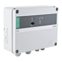
6.1 Front of the switchgear (Fig. 1)
6.2 Single components in the housing (Fig. 2)
5.1 Technical data
Mains supply voltages
1~ 230 V, 50/60 Hz
3~ 230 V, 50/60 Hz
3~ 400 V, 50/60 Hz
Max. current consumption
Wilo-Control
— ESK1:
— PSK1:
1-12 A
10-23 A
Protection class:
IP 54
Mains fuses
Control (230/400 V):
Low-voltage component:
0.1 A
0.8 A
Ambient temperature: -10 to +55 °C
Item Element Function
1 Signal lamp - green lights up continuously when mains voltage is available
2 Signal lamp - yellow
Depends on the selected operating mode:
– Displays “low water status”
– Lower level reached
lights up continuously when the electrodes are triggered
3 Signal lamp - red
Pump fault
lights up continuously when the pump is stopped due to an error.
4 Signal lamp - green
Pump in operation
lights up permanently while the pump is running
5 Three-way switch
Operating mode
Selecting the operating mode:
AUTO Automatic operation with all safety functions,
electronic motor protection, low-water protection
0Off
MANU button function
6 Pushbutton Resets the thermal overload protection
Item Element
1 Thermo-magnetic circuit breaker
2 12 V transformer for low voltage part
3 Motor protection
4 Terminal strip for external sensors (electrode, pressure switch, float switch, external control)
5 Earth contact
6 Variable adjustment of rated motor power in accordance with pump motor rating plate
7 Variable adjustment of electrode sensitivity to the hardness of the water
8 Variable adjustment of time delay for “low water status” display
9 Variable adjustment of time delay for pressure switch/flow meter
10 Fuse (0.1 A) for pre-selected voltage in accordance with pump motor rating plate
11 Protection class selector switch for low water protection
12 On/off switch for time delay when using pressure switch or flow meter
13 Connector for control panel circuit board
14 Fuse holder low voltage fuse (0.8 A)