Do you have a question about the Wilo ER 2 and is the answer not in the manual?
Describes the intended use of the switch unit for controlling low capacity pump units.
Provides detailed technical data and specifications for the control unit.
Explains the functionality and operation of the ER-Control Unit in managing multi-pump systems.
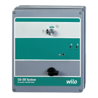
Details the components and indicators on the control unit's front panel.
Explains the various operational functions of the control unit, including overload protection and time delays.
Lists the items included in the standard supply package for the control unit.
Details the installation procedure for the control unit, noting it's supplied mounted.
Covers the electrical connections, terminal assignments, and wiring requirements.
Details the cause and reset procedure for a blinking green indicator light.
Explains the meaning of a red indicator light and its automatic reset condition.
Describes remote fault reporting for individual pumps via SM1 to SM4 terminals.
Covers collective fault signals and their relation to low water conditions and automatic reset.
| Brand | Wilo |
|---|---|
| Model | ER 2 |
| Category | Controller |
| Language | English |